Deploying HP FlexNetwork Core Technologies v7.0
Question 1
Four HP 3800 Series Switches have formed a backplane stack in aringtopology. Member 1 is the commander the two stacking links on the member 1 fail. What happens?
- A. If LACP Multi-Active Detection (MAD) is enabled and the stack connects to a ProVision switch on a link aggregation, member 2, 3 and 4 and shutdown the ports Otherwise, no ports are disabled
- B. If LACP Multi-Active Detection (MAD) is enabled member 1 shuts down all of its ports. Otherwise, no ports are disabled
- C. If the split policy is one-fragment-up member 1 shuts down all of its ports
- D. If the switch policy is one-fragment-up members 2, 3, and 4 shut down all of their ports
Answer : C
Explanation:
Inactive Stack fragment - The switches in this fragment do not actively switch packets.
They are powered on, however, the network
ceases to carry traffic. All user ports are disabled. Only the OOBM and stack ports remain active.
Note:Results of Disconnecting a Stacking Cable
If a stacking cable becomes disconnected from one of the switches in the stack, the effect depends on the stacking topology that is being used:
MeshThe stack topology is temporarily changed to a ring. To recover, simply reconnect the stacking cable; the mesh topology and the previous stack configuration is restored.
RingThere is little effect. The stack topology is temporarily changed to a chain topology.
To recover, simply reconnect the stacking cable; the ring topology and the previous stack configuration is restored.
ChainThe following occurs:
The smaller section (fragment) of the stack that results from the disconnection becomes Inactive(the Stack Status value shown in the output of the show stacking command is Inactive).
If the two resulting fragments are the same size, the fragment that contains the
Commander will be Active, and the other fragment becomes Inactive.
Both fragments will have a Commander and a Standby selected (if there is more than one switch in each fragment).
When the stacking cable is reconnected to reform the chain:
The Commander and Standby of the Active fragment retain those roles for the resulting stack. If the original Commander was not in that fragment, then the stack will have a new
Commander when the stack is reformed.
The switches in the Inactive fragment reboot and assume their new roles in the reformed chain.Stack fragment - A stack that previously had more members (that is, some of its previous members are now missing). The fragment can be Active or Inactive based on the rules described.
Active Stack fragment- When a stack becomes fragmented, only one fragment remains
Active; the other fragments become Inactive
(all network ports are disabled). The active stack fragment inherits the MAC address and IP addressing of the stack for management.The fragment that has more switches in it will be the Active fragment. This allows more of the network ports to remain operational. If the fragments have the same number of switches in them, then the fragment that has the original Commander will be the Active fragment.
Inactive Stack fragment - The switches in this fragment do not actively switch packets.
They are powered on, however, the network
ceases to carry traffic. All user ports are disabled. Only the OOBM and stack ports remain active.
Reference:Advanced Traffic Management Guide,3800 Switches
http://h20565.www2.hp.com/hpsc/doc/public/display?docId=emr_na-c03018186
Question 2
How does virtual output queuing (VoQ) help switches avoid head-of-line blocking and enhance throughput?
- A. It divides each port ingress queue into different queues based on the priority and egress port of each packet
- B. It establishes a matrix of connections to multiple cross-bar switches within the switch backplane
- C. It considers traffic congestion, queues traffic, and informs the ingress port when it can use the crossbar
- D. It allows the ingress port to fragment packets and send the fragments in multiple queues over different crossbars
Answer : A
Explanation: A Virtual Output Queue (VOQ) is the technique used in input-queued switches where rather than keeping all traffic in a single queue, separate queues are maintained for each possible output location. It addresses a common problem known as head-of-line blocking.
In VOQ each input port maintains a separate queue for each output port. It has been shown that VOQ can achieve 100% throughput performance with an effective scheduling algorithm. This scheduling algorithm should be able to provide a high speed mapping of packets from inputs to outputs on a cycle-to-cycle basis
Reference:https://en.wikipedia.org/wiki/Virtual_Output_Queues
Question 3
In which components of HP FlexNetwork solutions can Intelligent Resilient Framework
(IRF) play a role?
- A. IRF can operate at any layer of both campus and data center solutions.
- B. IRF can operate at the access layer of both campus and data center solutions. It cannot operate at the core.
- C. IRF can operate within data center solutions but not in campus solutions.
- D. IRF can operate at the core of both campus and data center solutions. It cannot operate at the access layer.
Answer : D
Explanation: HP FlexNetwork Architecture provides a common and consistent environment for enterprise data centers, campus and branch networks.
FlexCampus is based on a flat two-tieralso described as two-levelarchitecture.
Reference:https://en.wikipedia.org/wiki/HP_FlexNetwork_Architecture
Question 4
What distinguishes an HP switch with a CLOS fabric from an HP switch with a crossbar fabric?
- A. The CLOS fabric can integrate with a virtual switch, which is deployed in a virtualized server.
- B. The CLOS fabric is a requirement for an Intelligent Resilient Framework (IRF) virtual switch with more than two members.
- C. The CLOS fabric can dynamically shut down power to unused switch ports, proving better energy efficiency.
- D. The CLOS fabric can dynamically load-balance internal traffic over many paths, helping the switch support 40G/100G.
Answer : D
Explanation: Ina modernClos topology, every lower-tier switch is connected to each of the top-tier switches in a full-mesh topology. If there isn't any oversubscription taking place between the lower-tier switches and their uplinks, then a non-blocking architecture can be achieved. The advantage of the Clos network is you can use a set of identical and inexpensive devices to create the tree and gain high performance and resilience that would otherwise cost must more to construct. To prevent any one uplink path from being chosen, the path is randomly chosen so that the traffic load is evenly distributed between the top- tier switches. If one of the top tier switches were to fail, it only slightly degrades performance through the data center.
Reference: Clos Networks: What's Old Is New Again, What goes around, comes around
Clos Networks are back -
http://www.networkworld.com/article/2226122/cisco-subnet/clos-networks--what-s-old-is- new-again.html
Question 5
Refer to the exhibit.
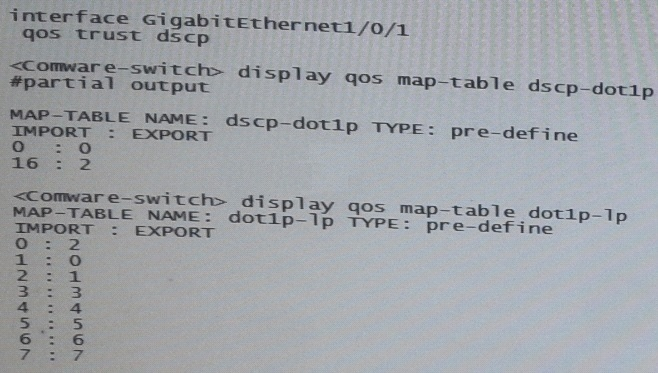
A server connects to GigabitEthernet1/0/1 on an HP Comware switch. The server sends tagged traffic in VLAN2. It has an application that sets the DiffServ Code Point (DSCP) for its traffic to 16 and the 802.1p value to 2. The switch should use the DSCP to place the traffic in priority queue.The traffic belongs to the queue that is one priority level higher than the queue for best effort traffic(traffic without a QoS value)
What can the network administrator do to meet this requirement?
- A. Change GigabitEthernet1/0/1s trust setting to dot1p set the port priority to 3.DSCP will not be used
- B. Keep Gigabit Ethernet1/0/1’s QoS trust setting to “dot1p” Set the port priority to 3.
- C. Change the dot1p-lp map to map 802.1p value 2 to lp 2 and 802.1p value0to lp1.
- D. Change the dscp-dot1p map to map DSCP 16 to 802.1p value 1.RECEIBE priority 0
Answer : C
Question 6
The network administrator is configuring Unidirectional Link Detection (UDLD) on trk1 on an HP Provision witch. The trk1 link aggregation group has these settings:
Interfaces = 48 and 49 -
Untagged VLAN = 1 -
Tagged VLANs = 2-4 -
How should the administrator complete the setup?
- A. Enable link-keepalive on both interfaces in the trunk (48 and 49).
- B. Enable link-keepalive on interface 48, specifying the VLAN as 1.
- C. On both interfaces in the trunk (48 and 49), enable link-keepalive, specifying the VLAN as 1.
- D. Enable link-keepalive on trk1
Answer : C
Explanation: * The following commands allow you to configure UDLD via the CLI.
Syntax: [no] interface <port-list> link-keepalive
Enables UDLD on a port or range of ports
* Ports enabled for UDLD exchange health-check packets once every five seconds (the link-keepalive interval). If a port does not receive a health-check packet from the port at the other end of the link within the keepalive interval, the port waits for four more intervals. If the port still does not receive a healthcheck packet after waiting for five intervals, the port concludes that the link has failed and blocks the UDLD-enabled port.
Reference:Port Status and Basic Configuration
ftp://ftp.hp.com/pub/networking/software/2900yl-MCG-0207-T_12_XX-Chap10-PrtStat-
BasicCfg.pdf -
Question 7
Refer to the exhibits.
Exhibit 1 -
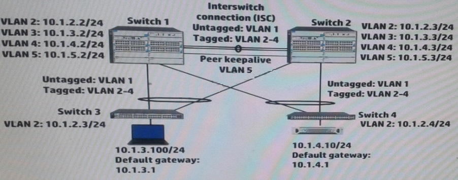
Exhibit 2 -
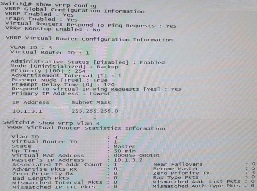
Exhibit 2 shows the Virtual Router Redundancy Protocol (VRRP) configuration and status for VLAN 3 on switch 1 during normal operation, when both Switch 1 and Switch 2 are up.
Switch 1 then experiences a power failure. After a few minutes, power is restored, and the switch comes back up.
What happens to VRRP operations in VLAN 3?
- A. Switch 1 becomes Master two minutes after its VRRP processes up.
- B. Switch 2 remains Master Switch 1 receives an error and stops participating in VRRP
- C. Switch 2 remains Master, and Switch 1 becomes a Backup router.
- D. Switch 1 becomes Master as soon as its VRRP processes come up.
Answer : C
Explanation:
Switch2 has priority 255, because Switch2(10.1.3.2) - MAster is up during 50 min, preempt is on in VRRP.SowhenSwitch1 comes online after 120min and trying to preeemtit will become theBackup Router
Question 8
A network administrator wants to configure Open Shortest Path (OSPF) MD5 authentication on VLAN 100 on an HP ProVision switch. The administrator has created a global MD5 key chain with an ID and key string that matchesthe neighbors. which additional step must the administrator complete to accomplish this?
- A. Set OSPF authentication to MD5 mode in the OSPF area settings
- B. Activate MD5 key rotation globally
- C. Enable MD5 key rotation globally
- D. Assign this MD5 key to OSPF VLAN 100
Answer : D
Explanation: Authentication-key: OSPF supports three methods of authentication for each interfacenone, simple password,and MD5. Only one method of authentication can be active on an interface at a time.
The MD5 method of authentication requires you to configure a key ID and an MD5 Key
Reference:Chapter 8,Configuring OSPF
http://www.hp.com/rnd/support/manuals/pdf/release_06628_07110/Bk2_Ch8_OSPF.pdf
Question 9
A company has a network with HP Provision switches. The network administrator is establishing remote mirroring session between two of the switches. The remote does not use the truncation option.
What must the administrator check on any switches between the mirror source and destination?
- A. The remote probe VLAN defined for the remote mirroring session extends across the switches.
- B. All switches transmit the remote mirroring traffic as untagged traffic.
- C. All switches transmit the remote mirroring traffic on single links, rather than link aggregations (or trunks).
- D. The VLANs that carry the remote mirroring traffic support jumbo frames.
Answer : D
Explanation: Configuring Jumbo Frame Support on ProCurve switches.
Details -
For remote traffic mirroring, enable jumbo frames to mirror Ethernet frames larger than
1464 bytes.
On both source and destination switches and any infrastructure switches in between
Mirrored frames sent to remote switch include an additional 54-byte mirror encapsulation header
5406zl(config)#vlan 10 jumbo Source switch
5412zl(config)#vlan 10 jumbo Intermediate switch
3500yl(config)#vlan 10 jumb0 Destination switch
When the source switch sends the mirrored data stream to the destination switch, it adds a
54-byte proprietary ("mirror encapsulation") header to the Layer 2 frame, increasing the total size of the frame.
Reference: ProCurve Switches - Remote Traffic Mirroring: Configuring Jumbo Frame
Support -
http://h20565.www2.hp.com/hpsc/doc/public/display?sp4ts.oid=82374&docId=emr_na- c02587751&docLocale=en_US
Question 10
A network administrator is configuring several HP Comware switches as an HP Intelligent
Resilient Framework(IRF) virtual device. According to best practices at, which point during the IRF configuration process should the administrator activate the IRF ports?
- A. After enabling the physical interfaces that are assigned to IRF ports and saving the settings
- B. After configuring IRF ports but before assigning physical interfaces to them
- C. After enabling the physical interfaces that are assigned to IRF ports but before saving the settings
- D. Before configuring IRF ports or assigning physical interfaces to them
Answer : A
Explanation:
(see steps 5 and 6 below)
Use theirf-port-configuration activecommand to activate configurations on all IRF ports on the device.
When you physically connect members of an IRF virtual device and bind physical IRF port(s) to an IRF port whose link state isDISorDOWN, which you can display with the display irf topologycommand, execution of this command is required to establish the IRF virtual device.
Note that activating IRF port configurations may cause merge of IRF virtual devices and automatic device reboot. Therefore, to avoid configuration loss you are recommended to set the member ID for the device in the following way:
1)Plan the network and member IDs in advance. Determine the number of IRF ports to be created, and which physical IRF ports is used for IRF virtual device establishment.
2)Change member IDs. (Member ID change takes effective after device reboot, so change member IDs before executing theirf-port-configuration activecommand.)
3)Connect SFP+ cables or fibers and make sure that the physical IRF ports are well connected.
4)Create IRF ports.
5)Bind physical IRF ports to IRF ports.
6)Save the current configurations to the configuration file to be used at the next startup.
7)Activate configurations on all IRF ports.
When the system starts up, if you bind a physical IRF port to an IRF port through the configuration file, or add a new physical port, configurations on IRF ports are automatically activated without the need to execute this command again.
Reference:IRF Configuration Commands
http://www.h3c.com/portal/Technical_Support___Documents/Technical_Documents/Voice_
Products/H3C_VG_Series_Voice_Gateway/Command/Command/0708test2/10/
Question 11
Refer to the exhibit.
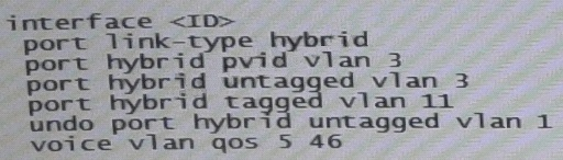
An HP Comware Switch connects to Voice over (VoIP) phones. The phones connect to users computes, so each switch port connects a computer and a phone.
These are the specifications:
-> The VLAN for data traffic is VLAN3
-> The VLAN for traffic VoIP is VLAN11
-> The phones support Link Layer Discovery Protocol (LLDP) Media Endpoint
Detection (MED).
The network administrator wants to use LLDP-MED to advertise the voice VLAN ID and priority settings to the phones. The phones will then send tagged traffic in that VLAN. The switch should not check the incoming traffics MAC address against its voice OID list. The exhibit shows the applicable switch port configuration.
Which additional step must the administrator complete to accomplish this?
- A. Enable voice VLAN 11 (voice vlan 11 enable)
- B. Change the port to trunk mode (port link-type trunk)
- C. Enable LLDP compatibility with Cisco Discovery Protocol (CDP) (lldp compliance admin- status cdp txrx)
- D. Enable the port to advertise voice VLAN 11 with LLDP (lldp voice-vlan 11)
Answer : D
Explanation: LLDPmust beenabled on thisEthernet ports and are configured to advertise the voice VLAN ID and QoSinformation using the Network Policy LLDP TLV.
Reference:Application Notesfor using Link Layer DiscoveryProtocol (LLDP) with HP
ProCurve Switches and Avaya IPTelephones - Issue 1.0
http://h17007.www1.hp.com/docs/interoperability/Avaya/ProCurve-lldp.pdf
Question 12
A company wants to enforce source-specific multicasting (SSM) for several multicast streams.
This is the configuration:
-> Some multicast receivers support IGMPv3.
-> Other receivers that need to stream support IGMPv2 only.
-> The multicast receivers' default routers enable IGMPv3 on the interfaces associated with their subnets.
-> The routers are correctly configured to enable the IGMPv3 receivers to receive the stream from the correct source
Which setting do the receivers' routers require to support the IGMPV2 devices?
- A. An SSM policy that selects the IGMPv2 devices and binds them to an RP address
- B. An SSM map that sets a rendezvous point (RP) for each multicast address
- C. An SSM policy that selects the appropriate multicast destinations and binds them to an RP address
- D. An SSM map that sets the correct source for each multicast address
Answer : D
Explanation: IGMP SSM mapping -
The IGMP SSM mapping feature provides SSM support for receiver hosts that are running
IGMPv1 or IGMPv2. This feature is implemented by configuring static IGMP SSM mappings on the IGMP-enabled routers.
The SSM model assumes that the IGMP-enabled routers have identified the desired multicast sources when receivers join multicast groups.
A host running IGMPv3 can explicitly specify multicast source addresses in its reports.
A host running IGMPv1 or IGMPv2, however, cannot specify multicast source addresses in its reports. In this case, you must configure the IGMP SSM mapping feature to translate the (*, G) information in the IGMPv1 or IGMPv2 reports into (G, INCLUDE, (S1, S2...)) information
Reference:HP MSR Router Series, IP Multicast Configuration Guide(V7) http://h20565.www2.hp.com/hpsc/doc/public/display?sp4ts.oid=6796027&docId=emr_na- c04412136&docLocale=en_US
Question 13
A company is determining whether HP IMC User Access manager (UAM) meets its needs for a RADIUS server. The company requires a solution for dynamic access control lists based on user identity and location (connected switch ID). Which statement correctly describes UAM support for this requirement?
- A. Administrator can use UAM service and access rules to apply identity-based ACLs. The location-based component is configured in individual switch CLIs.
- B. UAM can only meet these requirements if it is synchronized with Microsoft Active Directory (AD).
- C. UAM can meet these requirements if the company adds Endpoint Admission Defense (EAD) to the solution.
- D. Administrator can configure UAM service policies, scenarios, and access rules to meet these requirements.
Answer : D
Explanation: Endpoint Admission Defensecandynamically deploy ACLs to access devices for dynamic access control.
Endpoint Admission Defensee requires that a fullylicensed version of the HP IMC User
Access Management (UAM) software module be installed.
Reference:HP IMC Endpoint AdmissionDefense Software
http://h20195.www2.hp.com/V2/GetPDF.aspx/4AA3-0700ENW.pdf
Question 14
Match the characteristic to the routing protocol.
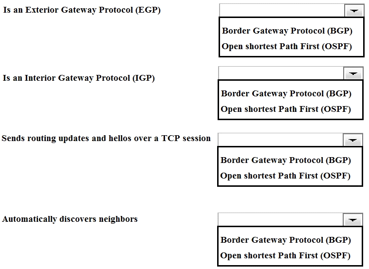
Answer : 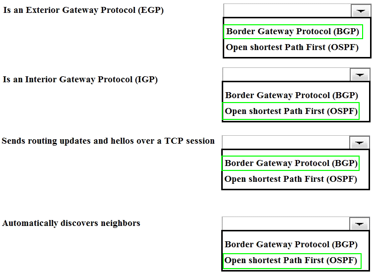
Question 15
Refer to the exhibits.
Exhibit1 -
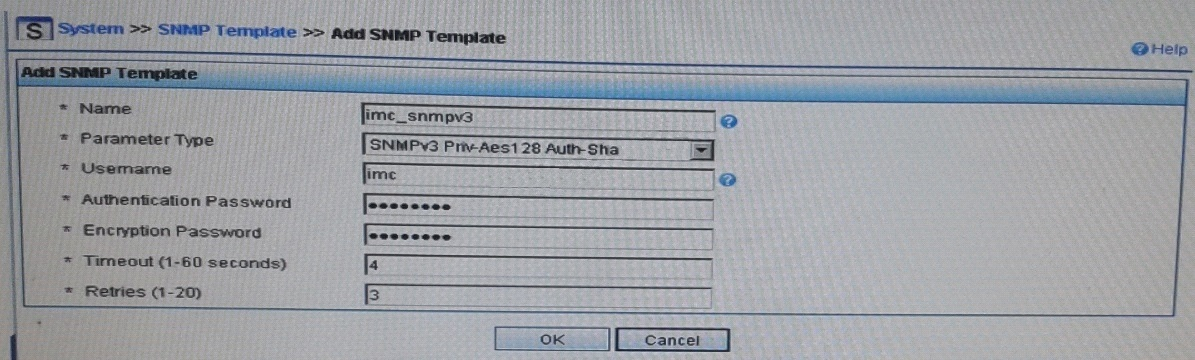
Exhibit 2 -
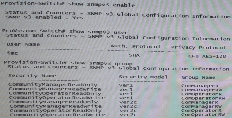
Exhibit 1 shows the SNMP template that HP Intelligent Management Center (IMC) will use when discovering an HP Provision switch. Exhibit 2showsettings on the switch.
IMC should have rights to read and write any parameter on the switch.
Which task must the network administrator complete to accomplish this?
- A. Create an MIB view and assign it to the “imc” user
- B. Enable the ver3 security model for the “CommunityManagerReadWrite” user
- C. Adding the “imc” user to the ManagerPriv group
- D. Change the “imc” user to ver2c mode
Answer : C
Explanation:
want to now create a more secure user, with SHA and AES-128
snmpv3 userimcauth shamysecurepasswordpriv aesmyprivpassword
Add the user to the managerpriv group
snmpv3 group managerpriv userimcsec-model ver3
Reference:SNMPv3 and IMC -
http://www.networktasks.co.uk/environments/hp/provision/snmpv3-and-imc