CCNP Troubleshooting and Maintaining Cisco IP Networks (TSHOOT v2.0) v1.0
Question 1
Instructions -
The main screen consists of two parts; the Main scenario and the Topology tabs. The main scenario describes TSHOOT.com test bed. The Topology tabs allow you to display the appropriate and select the trouble ticket.
To complete the item, you will first need to familiarize yourself with the TSHOOT.com test bed by clicking on the master scenario first and then the topologies tabs.
Once you are familiar with the test bed and the topologies, you should start evaluating the trouble ticket. You will be presented with a Trouble Ticket scenario that will describe the fault condition. You will need to determine on which device the fault condition is located, to which technology the fault condition is related, and the solution to each trouble ticket. This will be done by answering three questions.
Ticket Selection -
To begin, click on the Ticket on the Topology tabs.
Some of the questions will require you to use the scroll bar to see all options.
Please note.
Fault Isolation -
Read the ticket scenario to understand the fault condition.
Open the appropriate topology, based upon the ticket scenario.
Open the console of the desired device by clicking on that device in the topology, based upon your troubleshooting methodology.
Use the supported show, ping and trace commands to begin your fault isolation process.
Move to other devices as need by clicking on those devices within the topology.
Fault Identification -
The trouble ticket will include three questions that you will need to answer:
1. Which device contains the fault
2. Which technology the fault condition is related to
3. What is the solution to the issue
To advance to the next question within the ticket click on "Next Question".
When you click "DONE", the trouble ticket will turn RED and will no longer be accessible.
You may also use the "Previous Question" button to review questions within that specific ticket.
To complete a trouble ticket, answer all three questions and click "DONE". This will store your response to the questions. Do not click on "DONE" unless you have answered all questions within the ticket.
Item Completion -
Click the NEXT button on the bottom of the screen once a ticket is RED. This action moves you to the next item.
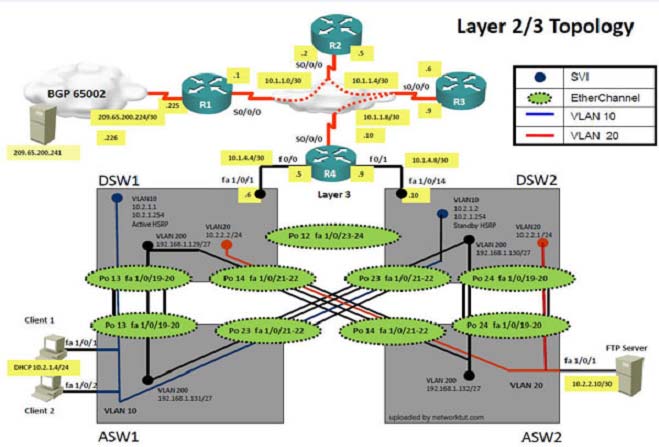
Topology Overview (Actual Troubleshooting lab design is for below network design)
Client Should have IP 10.2.1.3
EIGRP 100 is running between switch DSW1 & DSW2

OSPF (Process ID 1) is running between R1, R2, R3, R4
Network of OSPF is redistributed in EIGRP
BGP 65001 is configured on R1 with Webserver cloud AS 65002
HSRP is running between DSW1 & DSW2 Switches
The company has created the test bed shown in the layer 2 and layer 3 topology exhibits.
This network consists of four routers, two layer 3 switches and two layer 2 switches.
In the IPv4 layer 3 topology, R1, R2, R3, and R4 are running OSPF with an OSPF process number 1.
DSW1, DSW2 and R4 are running EIGRP with an AS of 10. Redistribution is enabled where necessary.
R1 is running a BGP AS with a number of 65001. This AS has an eBGP connection to AS 65002 in the ISP"™s network. Because the company"™s address space is in the private range.
R1 is also providing NAT translations between the inside (10.1.0.0/16 & 10.2.0.0/16) networks and outside (209.65.0.0/24) network.
ASW1 and ASW2 are layer 2 switches.
NTP is enabled on all devices with 209.65.200.226 serving as the master clock source.
The client workstations receive their IP address and default gateway via R4"™s DHCP server.
The default gateway address of 10.2.1.254 is the IP address of HSRP group 10 which is running on DSW1 and DSW2.
In the IPv6 layer 3 topology R1, R2, and R3 are running OSPFv3 with an OSPF process number 6.
DSW1, DSW2 and R4 are running RIPng process name RIP_ZONE.
The two IPv6 routing domains, OSPF 6 and RIPng are connected via GRE tunnel running over the underlying IPv4 OSPF domain. Redistrution is enabled where necessary.
Recently the implementation group has been using the test bed to do a "˜proof-of-concept"™ on several implementations. This involved changing the configuration on one or more of the devices. You will be presented with a series of trouble tickets related to issues introduced during these configurations.
Note: Although trouble tickets have many similar fault indications, each ticket has its own issue and solution.
Each ticket has 3 sub questions that need to be answered & topology remains same.
Fault is found on which device,
Question-1 -
Fault condition is related to,
Question-2 -
What exact problem is seen & what needs to be done for solution
Question-3 -

Client is unable to ping IP 209.65.200.241
Solution -
Steps need to follow as below:-
1. When we check on client 1 & Client 2 desktop we are not receiving DHCP address from R4
Ipconfig ----- Client will be receiving IP address 10.2.1.3
2. IP 10.2.1.3 will be able to ping from R4 , R3, R2, R1
3. Look for BGP Neighbourship
Sh ip bgp summary ----- State of BGP will be in established state & will be able to receive I prefix (209.65.200.241)
4. As per troubleshooting we are able to ping ip 10.2.1.3 from R1 & BGP is also receiving prefix of webserver & we are able to ping the same from R1. Further troubleshooting needs to be done on R1 on serial 0/0/1
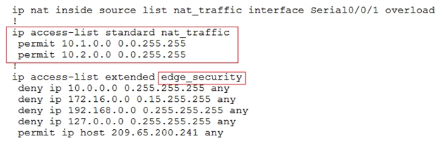
5. Check for running config. i.e sh run for interface serial 0/0/1.
!
!
From above snapshot we are able to see that IP needs to be PAT to serial 0/0/1 to reach web server IP
(209.65.200.241). But in access-list of NAT IP allowed IP is 10.1.0.0/16 is allowed & need 10.2.0.0 /16 to
6. As per troubleshooting we are able to ping ip 10.2.1.3 from R1 & BGP is also receiving prefix of web server & we are able to ping the same from R1. Its should be checked further for running config of interface for stopping
7. Change required: On R1 we need to add the client IP address for reachability to server to the access list that is used to specify which hosts get NATed.
The implementations group has been using the test bed to do a "˜proof-of-concept"™ that requires both Client 1 and Client 2 to access the WEB Server at
209.65.200.241. After several changes to the network addressing, routing schemes, DHCP services, NTP services, layer 2 connectivity, FHRP services, and device security, a trouble ticket has been opened indicating that Client 1 cannot ping the 209.65.200.241 address.
Use the supported commands to isolated the cause of this fault and answer the following questions.
On which device is the fault condition located?
- A. R1
- B. R2
- C. R3
- D. R4
- E. DSW1
- F. DSW2
- G. ASW1
Answer : A
Explanation:
On R1 we need to add the client IP address for reachability to server to the access list that is used to specify which hosts get NATed.
Question 2
Instructions -
The main screen consists of two parts; the Main scenario and the Topology tabs. The main scenario describes TSHOOT.com test bed. The Topology tabs allow you to display the appropriate and select the trouble ticket.
To complete the item, you will first need to familiarize yourself with the TSHOOT.com test bed by clicking on the master scenario first and then the topologies tabs.
Once you are familiar with the test bed and the topologies, you should start evaluating the trouble ticket. You will be presented with a Trouble Ticket scenario that will describe the fault condition. You will need to determine on which device the fault condition is located, to which technology the fault condition is related, and the solution to each trouble ticket. This will be done by answering three questions.
Ticket Selection -
To begin, click on the Ticket on the Topology tabs.
Some of the questions will require you to use the scroll bar to see all options.
Please note.
Fault Isolation -
Read the ticket scenario to understand the fault condition.
Open the appropriate topology, based upon the ticket scenario.
Open the console of the desired device by clicking on that device in the topology, based upon your troubleshooting methodology.
Use the supported show, ping and trace commands to begin your fault isolation process.
Move to other devices as need by clicking on those devices within the topology.
Fault Identification -
The trouble ticket will include three questions that you will need to answer:
1. Which device contains the fault
2. Which technology the fault condition is related to
3. What is the solution to the issue
To advance to the next question within the ticket click on "Next Question".
When you click "DONE", the trouble ticket will turn RED and will no longer be accessible.
You may also use the "Previous Question" button to review questions within that specific ticket.
To complete a trouble ticket, answer all three questions and click "DONE". This will store your response to the questions. Do not click on "DONE" unless you have answered all questions within the ticket.
Item Completion -
Click the NEXT button on the bottom of the screen once a ticket is RED. This action moves you to the next item.
Topology Overview (Actual Troubleshooting lab design is for below network design)
Client Should have IP 10.2.1.3
EIGRP 100 is running between switch DSW1 & DSW2
OSPF (Process ID 1) is running between R1, R2, R3, R4
Network of OSPF is redistributed in EIGRP
BGP 65001 is configured on R1 with Webserver cloud AS 65002
HSRP is running between DSW1 & DSW2 Switches
The company has created the test bed shown in the layer 2 and layer 3 topology exhibits.
This network consists of four routers, two layer 3 switches and two layer 2 switches.
In the IPv4 layer 3 topology, R1, R2, R3, and R4 are running OSPF with an OSPF process number 1.
DSW1, DSW2 and R4 are running EIGRP with an AS of 10. Redistribution is enabled where necessary.
R1 is running a BGP AS with a number of 65001. This AS has an eBGP connection to AS 65002 in the ISP"™s network. Because the company"™s address space is in the private range.
R1 is also providing NAT translations between the inside (10.1.0.0/16 & 10.2.0.0/16) networks and outside (209.65.0.0/24) network.
ASW1 and ASW2 are layer 2 switches.
NTP is enabled on all devices with 209.65.200.226 serving as the master clock source.
The client workstations receive their IP address and default gateway via R4"™s DHCP server.
The default gateway address of 10.2.1.254 is the IP address of HSRP group 10 which is running on DSW1 and DSW2.
In the IPv6 layer 3 topology R1, R2, and R3 are running OSPFv3 with an OSPF process number 6.
DSW1, DSW2 and R4 are running RIPng process name RIP_ZONE.
The two IPv6 routing domains, OSPF 6 and RIPng are connected via GRE tunnel running over the underlying IPv4 OSPF domain. Redistrution is enabled where necessary.
Recently the implementation group has been using the test bed to do a "˜proof-of-concept"™ on several implementations. This involved changing the configuration on one or more of the devices. You will be presented with a series of trouble tickets related to issues introduced during these configurations.
Note: Although trouble tickets have many similar fault indications, each ticket has its own issue and solution.
Each ticket has 3 sub questions that need to be answered & topology remains same.
Fault is found on which device,
Question-1 -
Fault condition is related to,
Question-2 -
What exact problem is seen & what needs to be done for solution
Question-3 -
Client is unable to ping IP 209.65.200.241
Solution -
Steps need to follow as below:-
1. When we check on client 1 & Client 2 desktop we are not receiving DHCP address from R4
Ipconfig ----- Client will be receiving IP address 10.2.1.3
2. IP 10.2.1.3 will be able to ping from R4 , R3, R2, R1
3. Look for BGP Neighbourship
Sh ip bgp summary ----- State of BGP will be in established state & will be able to receive I prefix (209.65.200.241)
4. As per troubleshooting we are able to ping ip 10.2.1.3 from R1 & BGP is also receiving prefix of webserver & we are able to ping the same from R1. Further troubleshooting needs to be done on R1 on serial 0/0/1
5. Check for running config. i.e sh run for interface serial 0/0/1.
!
!
From above snapshot we are able to see that IP needs to be PAT to serial 0/0/1 to reach web server IP
(209.65.200.241). But in access-list of NAT IP allowed IP is 10.1.0.0/16 is allowed & need 10.2.0.0 /16 to
6. As per troubleshooting we are able to ping ip 10.2.1.3 from R1 & BGP is also receiving prefix of web server & we are able to ping the same from R1. Its should be checked further for running config of interface for stopping
7. Change required: On R1 we need to add the client IP address for reachability to server to the access list that is used to specify which hosts get NATed.
The implementations group has been using the test bed to do a "˜proof-of-concept"™ that requires both Client 1 and Client 2 to access the WEB Server at
209.65.200.241. After several changes to the network addressing, routing scheme, DHCP services, NTP services, layer 2 connectivity, FHRP services, and device security, a trouble ticket has been opened indicating that Client 1 cannot ping the 209.65.200.241 address.
Use the supported commands to isolated the cause of this fault and answer the following questions.
The fault condition is related to which technology?
- A. BGP
- B. NTP
- C. IP NAT
- D. IPv4 OSPF Routing
- E. IPv4 OSPF Redistribution
- F. IPv6 OSPF Routing
- G. IPv4 layer 3 security
Answer : C
Explanation:
On R1 we need to add the client IP address for reachability to server to the access list that is used to specify which hosts get NATed.
Question 3
Instructions -
The main screen consists of two parts; the Main scenario and the Topology tabs. The main scenario describes TSHOOT.com test bed. The Topology tabs allow you to display the appropriate and select the trouble ticket.
To complete the item, you will first need to familiarize yourself with the TSHOOT.com test bed by clicking on the master scenario first and then the topologies tabs.
Once you are familiar with the test bed and the topologies, you should start evaluating the trouble ticket. You will be presented with a Trouble Ticket scenario that will describe the fault condition. You will need to determine on which device the fault condition is located, to which technology the fault condition is related, and the solution to each trouble ticket. This will be done by answering three questions.
Ticket Selection -
To begin, click on the Ticket on the Topology tabs.
Some of the questions will require you to use the scroll bar to see all options.
Please note.
Fault Isolation -
Read the ticket scenario to understand the fault condition.
Open the appropriate topology, based upon the ticket scenario.
Open the console of the desired device by clicking on that device in the topology, based upon your troubleshooting methodology.
Use the supported show, ping and trace commands to begin your fault isolation process.
Move to other devices as need by clicking on those devices within the topology.
Fault Identification -
The trouble ticket will include three questions that you will need to answer:
1. Which device contains the fault
2. Which technology the fault condition is related to
3. What is the solution to the issue
To advance to the next question within the ticket click on "Next Question".
When you click "DONE", the trouble ticket will turn RED and will no longer be accessible.
You may also use the "Previous Question" button to review questions within that specific ticket.
To complete a trouble ticket, answer all three questions and click "DONE". This will store your response to the questions. Do not click on "DONE" unless you have answered all questions within the ticket.
Item Completion -
Click the NEXT button on the bottom of the screen once a ticket is RED. This action moves you to the next item.
Topology Overview (Actual Troubleshooting lab design is for below network design)
Client Should have IP 10.2.1.3
EIGRP 100 is running between switch DSW1 & DSW2
OSPF (Process ID 1) is running between R1, R2, R3, R4
Network of OSPF is redistributed in EIGRP
BGP 65001 is configured on R1 with Webserver cloud AS 65002
HSRP is running between DSW1 & DSW2 Switches
The company has created the test bed shown in the layer 2 and layer 3 topology exhibits.
This network consists of four routers, two layer 3 switches and two layer 2 switches.
In the IPv4 layer 3 topology, R1, R2, R3, and R4 are running OSPF with an OSPF process number 1.
DSW1, DSW2 and R4 are running EIGRP with an AS of 10. Redistribution is enabled where necessary.
R1 is running a BGP AS with a number of 65001. This AS has an eBGP connection to AS 65002 in the ISP"™s network. Because the company"™s address space is in the private range.
R1 is also providing NAT translations between the inside (10.1.0.0/16 & 10.2.0.0/16) networks and outside (209.65.0.0/24) network.
ASW1 and ASW2 are layer 2 switches.
NTP is enabled on all devices with 209.65.200.226 serving as the master clock source.
The client workstations receive their IP address and default gateway via R4"™s DHCP server.
The default gateway address of 10.2.1.254 is the IP address of HSRP group 10 which is running on DSW1 and DSW2.
In the IPv6 layer 3 topology R1, R2, and R3 are running OSPFv3 with an OSPF process number 6.
DSW1, DSW2 and R4 are running RIPng process name RIP_ZONE.
The two IPv6 routing domains, OSPF 6 and RIPng are connected via GRE tunnel running over the underlying IPv4 OSPF domain. Redistrution is enabled where necessary.
Recently the implementation group has been using the test bed to do a "˜proof-of-concept"™ on several implementations. This involved changing the configuration on one or more of the devices. You will be presented with a series of trouble tickets related to issues introduced during these configurations.
Note: Although trouble tickets have many similar fault indications, each ticket has its own issue and solution.
Each ticket has 3 sub questions that need to be answered & topology remains same.
Fault is found on which device,
Question-1 -
Fault condition is related to,
Question-2 -
What exact problem is seen & what needs to be done for solution
Question-3 -
Client is unable to ping IP 209.65.200.241
Solution -
Steps need to follow as below:-
1. When we check on client 1 & Client 2 desktop we are not receiving DHCP address from R4
Ipconfig ----- Client will be receiving IP address 10.2.1.3
2. IP 10.2.1.3 will be able to ping from R4 , R3, R2, R1
3. Look for BGP Neighbourship
Sh ip bgp summary ----- State of BGP will be in established state & will be able to receive I prefix (209.65.200.241)
4. As per troubleshooting we are able to ping ip 10.2.1.3 from R1 & BGP is also receiving prefix of webserver & we are able to ping the same from R1. Further troubleshooting needs to be done on R1 on serial 0/0/1
5. Check for running config. i.e sh run for interface serial 0/0/1.
!
!
From above snapshot we are able to see that IP needs to be PAT to serial 0/0/1 to reach web server IP
(209.65.200.241). But in access-list of NAT IP allowed IP is 10.1.0.0/16 is allowed & need 10.2.0.0 /16 to
6. As per troubleshooting we are able to ping ip 10.2.1.3 from R1 & BGP is also receiving prefix of web server & we are able to ping the same from R1. Its should be checked further for running config of interface for stopping
7. Change required: On R1 we need to add the client IP address for reachability to server to the access list that is used to specify which hosts get NATed.
The implementations group has been using the test bed to do a "˜proof-of-concept"™ that requires both Client 1 and Client 2 to access the WEB Server at
209.65.200.241. After several changes to the network addressing, routing scheme, DHCP services, NTP services, layer 2 connectivity, FHRP services, and device security, a trouble ticket has been opened indicating that Client 1 cannot ping the 209.65.200.241 address.
Use the supported commands to isolated the cause of this fault and answer the following questions.
What is the solution to the fault condition?
- A. Under the interface Serial0/0/0 configuration enter the ip nat inside command.
- B. Under the interface Serial0/0/0 configuration enter the ip nat outside command.
- C. Under the ip access-list standard nat_trafic configuration enter the permit 10.2.0.0 0.0.255.255 command.
- D. Under the ip access-list standard nat_trafic configuration enter the permit 209.65.200.0 0.0.0.255 command.
Answer : C
Explanation:
On R1 we need to add the client IP address for reachability to server to the access list that is used to specify which hosts get NATed.
Question 4
Instructions -
The main screen consists of two parts; the Main scenario and the Topology tabs. The main scenario describes TSHOOT.com test bed. The Topology tabs allow you to display the appropriate and select the trouble ticket.
To complete the item, you will first need to familiarize yourself with the TSHOOT.com test bed by clicking on the master scenario first and then the topologies tabs.
Once you are familiar with the test bed and the topologies, you should start evaluating the trouble ticket. You will be presented with a Trouble Ticket scenario that will describe the fault condition. You will need to determine on which device the fault condition is located, to which technology the fault condition is related, and the solution to each trouble ticket. This will be done by answering three questions.
Ticket Selection -
To begin, click on the Ticket on the Topology tabs.
Some of the questions will require you to use the scroll bar to see all options.
Please note.
Fault Isolation -
Read the ticket scenario to understand the fault condition.
Open the appropriate topology, based upon the ticket scenario.
Open the console of the desired device by clicking on that device in the topology, based upon your troubleshooting methodology.
Use the supported show, ping and trace commands to begin your fault isolation process.
Move to other devices as need by clicking on those devices within the topology.
Fault Identification -
The trouble ticket will include three questions that you will need to answer:
1. Which device contains the fault
2. Which technology the fault condition is related to
3. What is the solution to the issue
To advance to the next question within the ticket click on "Next Question".
When you click "DONE", the trouble ticket will turn RED and will no longer be accessible.
You may also use the "Previous Question" button to review questions within that specific ticket.
To complete a trouble ticket, answer all three questions and click "DONE". This will store your response to the questions. Do not click on "DONE" unless you have answered all questions within the ticket.
Item Completion -
Click the NEXT button on the bottom of the screen once a ticket is RED. This action moves you to the next item.
Topology Overview (Actual Troubleshooting lab design is for below network design)
Client Should have IP 10.2.1.3
EIGRP 100 is running between switch DSW1 & DSW2

OSPF (Process ID 1) is running between R1, R2, R3, R4
Network of OSPF is redistributed in EIGRP
BGP 65001 is configured on R1 with Webserver cloud AS 65002
HSRP is running between DSW1 & DSW2 Switches
The company has created the test bed shown in the layer 2 and layer 3 topology exhibits.
This network consists of four routers, two layer 3 switches and two layer 2 switches.
In the IPv4 layer 3 topology, R1, R2, R3, and R4 are running OSPF with an OSPF process number 1.
DSW1, DSW2 and R4 are running EIGRP with an AS of 10. Redistribution is enabled where necessary.
R1 is running a BGP AS with a number of 65001. This AS has an eBGP connection to AS 65002 in the ISP"™s network. Because the company"™s address space is in the private range.
R1 is also providing NAT translations between the inside (10.1.0.0/16 & 10.2.0.0/16) networks and outside (209.65.0.0/24) network.
ASW1 and ASW2 are layer 2 switches.
NTP is enabled on all devices with 209.65.200.226 serving as the master clock source.
The client workstations receive their IP address and default gateway via R4"™s DHCP server.
The default gateway address of 10.2.1.254 is the IP address of HSRP group 10 which is running on DSW1 and DSW2.
In the IPv6 layer 3 topology R1, R2, and R3 are running OSPFv3 with an OSPF process number 6.
DSW1, DSW2 and R4 are running RIPng process name RIP_ZONE.
The two IPv6 routing domains, OSPF 6 and RIPng are connected via GRE tunnel running over the underlying IPv4 OSPF domain. Redistribution is enabled where necessary.
Recently the implementation group has been using the test bed to do a "˜proof-of-concept"™ on several implementations. This involved changing the configuration on one or more of the devices. You will be presented with a series of trouble tickets related to issues introduced during these configurations.
Note: Although trouble tickets have many similar fault indications, each ticket has its own issue and solution.
Each ticket has 3 sub questions that need to be answered & topology remains same.
Fault is found on which device,
Question-1 -
Fault condition is related to,
Question-2 -
What exact problem is seen & what needs to be done for solution
Question-3 -


Client is unable to ping IP 209.65.200.241"¦
Solution -
Steps need to follow as below:-
1. When we check on client 1 & Client 2 desktop we are not receiving DHCP address from R4
2. Ipconfig ----- Client will be receiving IP address 10.2.1.3
3. IP 10.2.1.3 will be able to ping from R4 , R3, R2, R1
4. Look for BGP Neighbourship
5. Sh ip bgp summary ----- State of BGP will be in active state. This means connectivity issue between serial
6. Check for running config. i.e sh run --- over here check for access-list configured on interface as BGP is down (No need to check for NAT configuration as its configuration should be right as first need to bring BGP up)
7. In above snapshot we can see that access-list of edge_security on R1 is not allowing wan IP network
8. Change required: On R1, we need to permit IP 209.65.200.222/30 under the access list.
The implementations group has been using the test bed to do a "˜proof-of-concept"™ that requires both Client 1 and Client 2 to access the WEB Server at
209.65.200.241. After several changes to the network addressing, routing scheme, DHCP services, NTP services, layer 2 connectivity, FHRP services, and device security, a trouble ticket has been opened indicating that Client 1 cannot ping the 209.65.200.241 address.
Use the supported commands to isolated the cause of this fault and answer the following questions.
On which device is the fault condition located?
- A. R1
- B. R2
- C. R3
- D. R4
- E. DSW1
- F. DSW2
- G. ASW1
Answer : A
Explanation:
On R1, we need to permit IP 209.65.200.222/30 under the access list.
Question 5
Instructions -
The main screen consists of two parts; the Main scenario and the Topology tabs. The main scenario describes TSHOOT.com test bed. The Topology tabs allow you to display the appropriate and select the trouble ticket.
To complete the item, you will first need to familiarize yourself with the TSHOOT.com test bed by clicking on the master scenario first and then the topologies tabs.
Once you are familiar with the test bed and the topologies, you should start evaluating the trouble ticket. You will be presented with a Trouble Ticket scenario that will describe the fault condition. You will need to determine on which device the fault condition is located, to which technology the fault condition is related, and the solution to each trouble ticket. This will be done by answering three questions.
Ticket Selection -
To begin, click on the Ticket on the Topology tabs.
Some of the questions will require you to use the scroll bar to see all options.
Please note.
Fault Isolation -
Read the ticket scenario to understand the fault condition.
Open the appropriate topology, based upon the ticket scenario.
Open the console of the desired device by clicking on that device in the topology, based upon your troubleshooting methodology.
Use the supported show, ping and trace commands to begin your fault isolation process.
Move to other devices as need by clicking on those devices within the topology.
Fault Identification -
The trouble ticket will include three questions that you will need to answer:
1. Which device contains the fault
2. Which technology the fault condition is related to
3. What is the solution to the issue
To advance to the next question within the ticket click on "Next Question".
When you click "DONE", the trouble ticket will turn RED and will no longer be accessible.
You may also use the "Previous Question" button to review questions within that specific ticket.
To complete a trouble ticket, answer all three questions and click "DONE". This will store your response to the questions. Do not click on "DONE" unless you have answered all questions within the ticket.
Item Completion -
Click the NEXT button on the bottom of the screen once a ticket is RED. This action moves you to the next item.
Topology Overview (Actual Troubleshooting lab design is for below network design)
Client Should have IP 10.2.1.3
EIGRP 100 is running between switch DSW1 & DSW2
OSPF (Process ID 1) is running between R1, R2, R3, R4
Network of OSPF is redistributed in EIGRP
BGP 65001 is configured on R1 with Webserver cloud AS 65002
HSRP is running between DSW1 & DSW2 Switches
The company has created the test bed shown in the layer 2 and layer 3 topology exhibits.
This network consists of four routers, two layer 3 switches and two layer 2 switches.
In the IPv4 layer 3 topology, R1, R2, R3, and R4 are running OSPF with an OSPF process number 1.
DSW1, DSW2 and R4 are running EIGRP with an AS of 10. Redistribution is enabled where necessary.
R1 is running a BGP AS with a number of 65001. This AS has an eBGP connection to AS 65002 in the ISP"™s network. Because the company"™s address space is in the private range.
R1 is also providing NAT translations between the inside (10.1.0.0/16 & 10.2.0.0/16) networks and outside (209.65.0.0/24) network.
ASW1 and ASW2 are layer 2 switches.
NTP is enabled on all devices with 209.65.200.226 serving as the master clock source.
The client workstations receive their IP address and default gateway via R4"™s DHCP server.
The default gateway address of 10.2.1.254 is the IP address of HSRP group 10 which is running on DSW1 and DSW2.
In the IPv6 layer 3 topology R1, R2, and R3 are running OSPFv3 with an OSPF process number 6.
DSW1, DSW2 and R4 are running RIPng process name RIP_ZONE.
The two IPv6 routing domains, OSPF 6 and RIPng are connected via GRE tunnel running over the underlying IPv4 OSPF domain. Redistribution is enabled where necessary.
Recently the implementation group has been using the test bed to do a "˜proof-of-concept"™ on several implementations. This involved changing the configuration on one or more of the devices. You will be presented with a series of trouble tickets related to issues introduced during these configurations.
Note: Although trouble tickets have many similar fault indications, each ticket has its own issue and solution.
Each ticket has 3 sub questions that need to be answered & topology remains same.
Fault is found on which device,
Question-1 -
Fault condition is related to,
Question-2 -
What exact problem is seen & what needs to be done for solution
Question-3 -
Client is unable to ping IP 209.65.200.241"¦
Solution -
Steps need to follow as below:-
1. When we check on client 1 & Client 2 desktop we are not receiving DHCP address from R4
2. Ipconfig ----- Client will be receiving IP address 10.2.1.3
3. IP 10.2.1.3 will be able to ping from R4 , R3, R2, R1
4. Look for BGP Neighbourship
5. Sh ip bgp summary ----- State of BGP will be in active state. This means connectivity issue between serial
6. Check for running config. i.e sh run --- over here check for access-list configured on interface as BGP is down (No need to check for NAT configuration as its configuration should be right as first need to bring BGP up)
7. In above snapshot we can see that access-list of edge_security on R1 is not allowing wan IP network
8. Change required: On R1, we need to permit IP 209.65.200.222/30 under the access list.
The implementations group has been using the test bed to do a "˜proof-of-concept"™ that requires both Client 1 and Client 2 to access the WEB Server at
209.65.200.241. After several changes to the network addressing, routing scheme, DHCP services, NTP services, layer 2 connectivity, FHRP services, and device security, a trouble ticket has been opened indicating that Client 1 cannot ping the 209.65.200.241 address.
Use the supported commands to isolated the cause of this fault and answer the following questions.
The fault condition is related to which technology?
- A. BGP
- B. NTP
- C. IP NAT
- D. IPv4 OSPF Routing
- E. IPv4 OSPF Redistribution
- F. IPv6 OSPF Routing
- G. IPv4 layer 3 security
Answer : G
Explanation:
On R1, we need to permit IP 209.65.200.222/30 under the access list.
Question 6
Instructions -
The main screen consists of two parts; the Main scenario and the Topology tabs. The main scenario describes TSHOOT.com test bed. The Topology tabs allow you to display the appropriate and select the trouble ticket.
To complete the item, you will first need to familiarize yourself with the TSHOOT.com test bed by clicking on the master scenario first and then the topologies tabs.
Once you are familiar with the test bed and the topologies, you should start evaluating the trouble ticket. You will be presented with a Trouble Ticket scenario that will describe the fault condition. You will need to determine on which device the fault condition is located, to which technology the fault condition is related, and the solution to each trouble ticket. This will be done by answering three questions.
Ticket Selection -
To begin, click on the Ticket on the Topology tabs.
Some of the questions will require you to use the scroll bar to see all options.
Please note.
Fault Isolation -
Read the ticket scenario to understand the fault condition.
Open the appropriate topology, based upon the ticket scenario.
Open the console of the desired device by clicking on that device in the topology, based upon your troubleshooting methodology.
Use the supported show, ping and trace commands to begin your fault isolation process.
Move to other devices as need by clicking on those devices within the topology.
Fault Identification -
The trouble ticket will include three questions that you will need to answer:
1. Which device contains the fault
2. Which technology the fault condition is related to
3. What is the solution to the issue
To advance to the next question within the ticket click on "Next Question".
When you click "DONE", the trouble ticket will turn RED and will no longer be accessible.
You may also use the "Previous Question" button to review questions within that specific ticket.
To complete a trouble ticket, answer all three questions and click "DONE". This will store your response to the questions. Do not click on "DONE" unless you have answered all questions within the ticket.
Item Completion -
Click the NEXT button on the bottom of the screen once a ticket is RED. This action moves you to the next item.
Topology Overview (Actual Troubleshooting lab design is for below network design)
Client Should have IP 10.2.1.3
EIGRP 100 is running between switch DSW1 & DSW2
OSPF (Process ID 1) is running between R1, R2, R3, R4
Network of OSPF is redistributed in EIGRP
BGP 65001 is configured on R1 with Webserver cloud AS 65002
HSRP is running between DSW1 & DSW2 Switches
The company has created the test bed shown in the layer 2 and layer 3 topology exhibits.
This network consists of four routers, two layer 3 switches and two layer 2 switches.
In the IPv4 layer 3 topology, R1, R2, R3, and R4 are running OSPF with an OSPF process number 1.
DSW1, DSW2 and R4 are running EIGRP with an AS of 10. Redistribution is enabled where necessary.
R1 is running a BGP AS with a number of 65001. This AS has an eBGP connection to AS 65002 in the ISP"™s network. Because the company"™s address space is in the private range.
R1 is also providing NAT translations between the inside (10.1.0.0/16 & 10.2.0.0/16) networks and outside (209.65.0.0/24) network.
ASW1 and ASW2 are layer 2 switches.
NTP is enabled on all devices with 209.65.200.226 serving as the master clock source.
The client workstations receive their IP address and default gateway via R4"™s DHCP server.
The default gateway address of 10.2.1.254 is the IP address of HSRP group 10 which is running on DSW1 and DSW2.
In the IPv6 layer 3 topology R1, R2, and R3 are running OSPFv3 with an OSPF process number 6.
DSW1, DSW2 and R4 are running RIPng process name RIP_ZONE.
The two IPv6 routing domains, OSPF 6 and RIPng are connected via GRE tunnel running over the underlying IPv4 OSPF domain. Redistribution is enabled where necessary.
Recently the implementation group has been using the test bed to do a "˜proof-of-concept"™ on several implementations. This involved changing the configuration on one or more of the devices. You will be presented with a series of trouble tickets related to issues introduced during these configurations.
Note: Although trouble tickets have many similar fault indications, each ticket has its own issue and solution.
Each ticket has 3 sub questions that need to be answered & topology remains same.
Fault is found on which device,
Question-1 -
Fault condition is related to,
Question-2 -
What exact problem is seen & what needs to be done for solution
Question-3 -
Client is unable to ping IP 209.65.200.241"¦
Solution -
Steps need to follow as below:-
1. When we check on client 1 & Client 2 desktop we are not receiving DHCP address from R4
2. Ipconfig ----- Client will be receiving IP address 10.2.1.3
3. IP 10.2.1.3 will be able to ping from R4 , R3, R2, R1
4. Look for BGP Neighbourship
5. Sh ip bgp summary ----- State of BGP will be in active state. This means connectivity issue between serial
6. Check for running config. i.e sh run --- over here check for access-list configured on interface as BGP is down (No need to check for NAT configuration as its configuration should be right as first need to bring BGP up)
7. In above snapshot we can see that access-list of edge_security on R1 is not allowing wan IP network
8. Change required: On R1, we need to permit IP 209.65.200.222/30 under the access list.
The implementations group has been using the test bed to do a "˜proof-of-concept"™ that requires both Client 1 and Client 2 to access the WEB Server at
209.65.200.241. After several changes to the network addressing, routing scheme, DHCP services, NTP services, layer 2 connectivity, FHRP services, and device security, a trouble ticket has been opened indicating that Client 1 cannot ping the 209.65.200.241 address.
Use the supported commands to isolated the cause of this fault and answer the following questions.
What is the solution to the fault condition?
- A. Under the interface Serial0/0/1 enter the ip access-group edge_security out command.
- B. Under the ip access-list extended edge_security configuration add the permit ip 209.65.200.224 0.0.0.3 any command.
- C. Under the ip access-list extended edge_security configuration delete the deny ip 10.0.0.0.0 0.255.255.255 any command.
- D. Under the interface Serial0/0/0 configuration delete the ip access-group edge_security in command and enter the ip access-group edge_security out command.
Answer : B
Explanation:
On R1, we need to permit IP 209.65.200.222/30 under the access list.
Question 7
Instructions -
The main screen consists of two parts; the Main scenario and the Topology tabs. The main scenario describes TSHOOT.com test bed. The Topology tabs allow you to display the appropriate and select the trouble ticket.
To complete the item, you will first need to familiarize yourself with the TSHOOT.com test bed by clicking on the master scenario first and then the topologies tabs.
Once you are familiar with the test bed and the topologies, you should start evaluating the trouble ticket. You will be presented with a Trouble Ticket scenario that will describe the fault condition. You will need to determine on which device the fault condition is located, to which technology the fault condition is related, and the solution to each trouble ticket. This will be done by answering three questions.
Ticket Selection -
To begin, click on the Ticket on the Topology tabs.
Some of the questions will require you to use the scroll bar to see all options.
Please note.
Fault Isolation -
Read the ticket scenario to understand the fault condition.
Open the appropriate topology, based upon the ticket scenario.
Open the console of the desired device by clicking on that device in the topology, based upon your troubleshooting methodology.
Use the supported show, ping and trace commands to begin your fault isolation process.
Move to other devices as need by clicking on those devices within the topology.
Fault Identification -
The trouble ticket will include three questions that you will need to answer:
1. Which device contains the fault
2. Which technology the fault condition is related to
3. What is the solution to the issue
To advance to the next question within the ticket click on "Next Question".
When you click "DONE", the trouble ticket will turn RED and will no longer be accessible.
You may also use the "Previous Question" button to review questions within that specific ticket.
To complete a trouble ticket, answer all three questions and click "DONE". This will store your response to the questions. Do not click on "DONE" unless you have answered all questions within the ticket.
Item Completion -
Click the NEXT button on the bottom of the screen once a ticket is RED. This action moves you to the next item.
Topology Overview (Actual Troubleshooting lab design is for below network design)
Client Should have IP 10.2.1.3
EIGRP 100 is running between switch DSW1 & DSW2

OSPF (Process ID 1) is running between R1, R2, R3, R4
Network of OSPF is redistributed in EIGRP
BGP 65001 is configured on R1 with Webserver cloud AS 65002
HSRP is running between DSW1 & DSW2 Switches
The company has created the test bed shown in the layer 2 and layer 3 topology exhibits.
This network consists of four routers, two layer 3 switches and two layer 2 switches.
In the IPv4 layer 3 topology, R1, R2, R3, and R4 are running OSPF with an OSPF process number 1.
DSW1, DSW2 and R4 are running EIGRP with an AS of 10. Redistribution is enabled where necessary.
R1 is running a BGP AS with a number of 65001. This AS has an eBGP connection to AS 65002 in the ISP"™s network. Because the company"™s address space is in the private range.
R1 is also providing NAT translations between the inside (10.1.0.0/16 & 10.2.0.0/16) networks and outside (209.65.0.0/24) network.
ASW1 and ASW2 are layer 2 switches.
NTP is enabled on all devices with 209.65.200.226 serving as the master clock source.
The client workstations receive their IP address and default gateway via R4"™s DHCP server.
The default gateway address of 10.2.1.254 is the IP address of HSRP group 10 which is running on DSW1 and DSW2.
In the IPv6 layer 3 topology R1, R2, and R3 are running OSPFv3 with an OSPF process number 6.
DSW1, DSW2 and R4 are running RIPng process name RIP_ZONE.
The two IPv6 routing domains, OSPF 6 and RIPng are connected via GRE tunnel running over the underlying IPv4 OSPF domain. Redistrution is enabled where necessary.
Recently the implementation group has been using the test bed to do a "˜proof-of-concept"™ on several implementations. This involved changing the configuration on one or more of the devices. You will be presented with a series of trouble tickets related to issues introduced during these configurations.
Note: Although trouble tickets have many similar fault indications, each ticket has its own issue and solution.
Each ticket has 3 sub questions that need to be answered & topology remains same.
Fault is found on which device,
Question-1 -
Fault condition is related to,
Question-2 -
What exact problem is seen & what needs to be done for solution
Question-3 -
===============================================================================


Client is unable to ping IP 209.65.200.241
Solution -
Steps need to follow as below:-
1. When we check on client 1 & Client 2 desktop we are not receiving DHCP address from R4 ipconfig ----- Client will be getting 169.X.X.X
2. On ASW1 port Fa1/0/ 1 & Fa1/0/2 access port VLAN 10 was assigned but when we checked interface it was showing down
Sh run ------- check for running config of int fa1/0/1 & fa1/0/2 (switchport access Vlan 10 will be there with switch port security command). Now check as below
Sh int fa1/0/1 & sh int fa1/0/2 -
3. As seen on interface the port is in err-disable mode so need to clear port.
4. Change required: On ASW1, we need to remove port-security under interface fa1/0/1 & fa1/0/2.
------------------------------------------------------------------------------------------------------------------------------
The implementations group has been using the test bed to do a "˜proof-of-concept"™ that requires both Client 1 and Client 2 to access the WEB Server at
209.65.200.241. After several changes to the network addressing, routing scheme, DHCP services, NTP services, layer 2 connectivity, FHRP services, and device security, a trouble ticket has been opened indicating that Client 1 cannot ping the 209.65.200.241 address.
Use the supported commands to isolated the cause of this fault and answer the following questions.
On which device is the fault condition located?
- A. R1
- B. R2
- C. R3
- D. R4
- E. DSW1
- F. DSW2
- G. ASW1
- H. ASW2
Answer : G
Explanation:
port security needs is configured on ASW1.
Question 8
Instructions -
The main screen consists of two parts; the Main scenario and the Topology tabs. The main scenario describes TSHOOT.com test bed. The Topology tabs allow you to display the appropriate and select the trouble ticket.
To complete the item, you will first need to familiarize yourself with the TSHOOT.com test bed by clicking on the master scenario first and then the topologies tabs.
Once you are familiar with the test bed and the topologies, you should start evaluating the trouble ticket. You will be presented with a Trouble Ticket scenario that will describe the fault condition. You will need to determine on which device the fault condition is located, to which technology the fault condition is related, and the solution to each trouble ticket. This will be done by answering three questions.
Ticket Selection -
To begin, click on the Ticket on the Topology tabs.
Some of the questions will require you to use the scroll bar to see all options.
Please note.
Fault Isolation -
Read the ticket scenario to understand the fault condition.
Open the appropriate topology, based upon the ticket scenario.
Open the console of the desired device by clicking on that device in the topology, based upon your troubleshooting methodology.
Use the supported show, ping and trace commands to begin your fault isolation process.
Move to other devices as need by clicking on those devices within the topology.
Fault Identification -
The trouble ticket will include three questions that you will need to answer:
1. Which device contains the fault
2. Which technology the fault condition is related to
3. What is the solution to the issue
To advance to the next question within the ticket click on "Next Question".
When you click "DONE", the trouble ticket will turn RED and will no longer be accessible.
You may also use the "Previous Question" button to review questions within that specific ticket.
To complete a trouble ticket, answer all three questions and click "DONE". This will store your response to the questions. Do not click on "DONE" unless you have answered all questions within the ticket.
Item Completion -
Click the NEXT button on the bottom of the screen once a ticket is RED. This action moves you to the next item.
Topology Overview (Actual Troubleshooting lab design is for below network design)
Client Should have IP 10.2.1.3
EIGRP 100 is running between switch DSW1 & DSW2
OSPF (Process ID 1) is running between R1, R2, R3, R4
Network of OSPF is redistributed in EIGRP
BGP 65001 is configured on R1 with Webserver cloud AS 65002
HSRP is running between DSW1 & DSW2 Switches
The company has created the test bed shown in the layer 2 and layer 3 topology exhibits.
This network consists of four routers, two layer 3 switches and two layer 2 switches.
In the IPv4 layer 3 topology, R1, R2, R3, and R4 are running OSPF with an OSPF process number 1.
DSW1, DSW2 and R4 are running EIGRP with an AS of 10. Redistribution is enabled where necessary.
R1 is running a BGP AS with a number of 65001. This AS has an eBGP connection to AS 65002 in the ISP"™s network. Because the company"™s address space is in the private range.
R1 is also providing NAT translations between the inside (10.1.0.0/16 & 10.2.0.0/16) networks and outside (209.65.0.0/24) network.
ASW1 and ASW2 are layer 2 switches.
NTP is enabled on all devices with 209.65.200.226 serving as the master clock source.
The client workstations receive their IP address and default gateway via R4"™s DHCP server.
The default gateway address of 10.2.1.254 is the IP address of HSRP group 10 which is running on DSW1 and DSW2.
In the IPv6 layer 3 topology R1, R2, and R3 are running OSPFv3 with an OSPF process number 6.
DSW1, DSW2 and R4 are running RIPng process name RIP_ZONE.
The two IPv6 routing domains, OSPF 6 and RIPng are connected via GRE tunnel running over the underlying IPv4 OSPF domain. Redistrution is enabled where necessary.
Recently the implementation group has been using the test bed to do a "˜proof-of-concept"™ on several implementations. This involved changing the configuration on one or more of the devices. You will be presented with a series of trouble tickets related to issues introduced during these configurations.
Note: Although trouble tickets have many similar fault indications, each ticket has its own issue and solution.
Each ticket has 3 sub questions that need to be answered & topology remains same.
Fault is found on which device,
Question-1 -
Fault condition is related to,
Question-2 -
What exact problem is seen & what needs to be done for solution
Question-3 -
===============================================================================
Client is unable to ping IP 209.65.200.241
Solution -
Steps need to follow as below:-
1. When we check on client 1 & Client 2 desktop we are not receiving DHCP address from R4 ipconfig ----- Client will be getting 169.X.X.X
2. On ASW1 port Fa1/0/ 1 & Fa1/0/2 access port VLAN 10 was assigned but when we checked interface it was showing down
Sh run ------- check for running config of int fa1/0/1 & fa1/0/2 (switchport access Vlan 10 will be there with switch port security command). Now check as below
Sh int fa1/0/1 & sh int fa1/0/2 -
3. As seen on interface the port is in err-disable mode so need to clear port.
4. Change required: On ASW1, we need to remove port-security under interface fa1/0/1 & fa1/0/2.
------------------------------------------------------------------------------------------------------------------------------
The implementations group has been using the test bed to do a "˜proof-of-concept"™ that requires both Client 1 and Client 2 to access the WEB Server at
209.65.200.241. After several changes to the network addressing, routing scheme, DHCP services, NTP services, layer 2 connectivity, FHRP services, and device security, a trouble ticket has been opened indicating that Client 1 cannot ping the 209.65.200.241 address.
Use the supported commands to isolated the cause of this fault and answer the following questions.
The fault condition is related to which technology?
- A. NTP
- B. Switch-to-Switch Connectivity
- C. Access Vlans
- D. Port Security
- E. VLAN ACL / Port ACL
- F. Switch Virtual Interface
Answer : D
Explanation:
Port security is causing the connectivity issues. On ASW1, we need to remove port-security under interface fa1/0/1 & fa1/0/2.
Question 9
Instructions -
The main screen consists of two parts; the Main scenario and the Topology tabs. The main scenario describes TSHOOT.com test bed. The Topology tabs allow you to display the appropriate and select the trouble ticket.
To complete the item, you will first need to familiarize yourself with the TSHOOT.com test bed by clicking on the master scenario first and then the topologies tabs.
Once you are familiar with the test bed and the topologies, you should start evaluating the trouble ticket. You will be presented with a Trouble Ticket scenario that will describe the fault condition. You will need to determine on which device the fault condition is located, to which technology the fault condition is related, and the solution to each trouble ticket. This will be done by answering three questions.
Ticket Selection -
To begin, click on the Ticket on the Topology tabs.
Some of the questions will require you to use the scroll bar to see all options.
Please note.
Fault Isolation -
Read the ticket scenario to understand the fault condition.
Open the appropriate topology, based upon the ticket scenario.
Open the console of the desired device by clicking on that device in the topology, based upon your troubleshooting methodology.
Use the supported show, ping and trace commands to begin your fault isolation process.
Move to other devices as need by clicking on those devices within the topology.
Fault Identification -
The trouble ticket will include three questions that you will need to answer:
1. Which device contains the fault
2. Which technology the fault condition is related to
3. What is the solution to the issue
To advance to the next question within the ticket click on "Next Question".
When you click "DONE", the trouble ticket will turn RED and will no longer be accessible.
You may also use the "Previous Question" button to review questions within that specific ticket.
To complete a trouble ticket, answer all three questions and click "DONE". This will store your response to the questions. Do not click on "DONE" unless you have answered all questions within the ticket.
Item Completion -
Click the NEXT button on the bottom of the screen once a ticket is RED. This action moves you to the next item.
Topology Overview (Actual Troubleshooting lab design is for below network design)
Client Should have IP 10.2.1.3
EIGRP 100 is running between switch DSW1 & DSW2
OSPF (Process ID 1) is running between R1, R2, R3, R4
Network of OSPF is redistributed in EIGRP
BGP 65001 is configured on R1 with Webserver cloud AS 65002
HSRP is running between DSW1 & DSW2 Switches
The company has created the test bed shown in the layer 2 and layer 3 topology exhibits.
This network consists of four routers, two layer 3 switches and two layer 2 switches.
In the IPv4 layer 3 topology, R1, R2, R3, and R4 are running OSPF with an OSPF process number 1.
DSW1, DSW2 and R4 are running EIGRP with an AS of 10. Redistribution is enabled where necessary.
R1 is running a BGP AS with a number of 65001. This AS has an eBGP connection to AS 65002 in the ISP"™s network. Because the company"™s address space is in the private range.
R1 is also providing NAT translations between the inside (10.1.0.0/16 & 10.2.0.0/16) networks and outside (209.65.0.0/24) network.
ASW1 and ASW2 are layer 2 switches.
NTP is enabled on all devices with 209.65.200.226 serving as the master clock source.
The client workstations receive their IP address and default gateway via R4"™s DHCP server.
The default gateway address of 10.2.1.254 is the IP address of HSRP group 10 which is running on DSW1 and DSW2.
In the IPv6 layer 3 topology R1, R2, and R3 are running OSPFv3 with an OSPF process number 6.
DSW1, DSW2 and R4 are running RIPng process name RIP_ZONE.
The two IPv6 routing domains, OSPF 6 and RIPng are connected via GRE tunnel running over the underlying IPv4 OSPF domain. Redistrution is enabled where necessary.
Recently the implementation group has been using the test bed to do a "˜proof-of-concept"™ on several implementations. This involved changing the configuration on one or more of the devices. You will be presented with a series of trouble tickets related to issues introduced during these configurations.
Note: Although trouble tickets have many similar fault indications, each ticket has its own issue and solution.
Each ticket has 3 sub questions that need to be answered & topology remains same.
Fault is found on which device,
Question-1 -
Fault condition is related to,
Question-2 -
What exact problem is seen & what needs to be done for solution
Question-3 -
===============================================================================
Client is unable to ping IP 209.65.200.241
Solution -
Steps need to follow as below:-
1. When we check on client 1 & Client 2 desktop we are not receiving DHCP address from R4 ipconfig ----- Client will be getting 169.X.X.X
2. On ASW1 port Fa1/0/ 1 & Fa1/0/2 access port VLAN 10 was assigned but when we checked interface it was showing down
Sh run ------- check for running config of int fa1/0/1 & fa1/0/2 (switchport access Vlan 10 will be there with switch port security command). Now check as below
Sh int fa1/0/1 & sh int fa1/0/2 -
3. As seen on interface the port is in err-disable mode so need to clear port.
4. Change required: On ASW1, we need to remove port-security under interface fa1/0/1 & fa1/0/2.
------------------------------------------------------------------------------------------------------------------------------
The implementations group has been using the test bed to do a "˜proof-of-concept"™ that requires both Client 1 and Client 2 to access the WEB Server at
209.65.200.241. After several changes to the network addressing, routing scheme, DHCP services, NTP services, layer 2 connectivity, FHRP services, and device security, a trouble ticket has been opened indicating that Client 1 cannot ping the 209.65.200.241 address.
Use the supported commands to isolated the cause of this fault and answer the following questions.
What is the solution to the fault condition?
- A. In Configuration mode, using the interface range Fa 1/0/1 "" 2, then no switchport port-security interface configuration commands. Then in exec mode clear errdisable interface fa 1/01 "" 2 vlan 10 command
- B. In Configuration mode, using the interface range Fa 1/0/1 "" 2, then no switchport port-security, followed by shutdown, no shutdown interface configuration commands.
- C. In Configuration mode, using the interface range Fa 1/0/1 "" 2, then no switchport port-security interface configuration commands.
- D. In Configuration mode, using the interface range Fa 1/0/1 "" 2, then no switchport port-security interface configuration commands. Then in exec mode clear errdisable interface fa 1/0/1, then clear errdisable interface fa 1/0/2 commands.
Answer : B
Explanation:
On ASW1, we need to remove port-security under interface fa1/0/1 & fa1/0/2.
Question 10
Instructions -
The main screen consists of two parts; the Main scenario and the Topology tabs. The main scenario describes TSHOOT.com test bed. The Topology tabs allow you to display the appropriate and select the trouble ticket.
To complete the item, you will first need to familiarize yourself with the TSHOOT.com test bed by clicking on the master scenario first and then the topologies tabs.
Once you are familiar with the test bed and the topologies, you should start evaluating the trouble ticket. You will be presented with a Trouble Ticket scenario that will describe the fault condition. You will need to determine on which device the fault condition is located, to which technology the fault condition is related, and the solution to each trouble ticket. This will be done by answering three questions.
Ticket Selection -
To begin, click on the Ticket on the Topology tabs.
Some of the questions will require you to use the scroll bar to see all options.
Please note.
Fault Isolation -
Read the ticket scenario to understand the fault condition.
Open the appropriate topology, based upon the ticket scenario.
Open the console of the desired device by clicking on that device in the topology, based upon your troubleshooting methodology.
Use the supported show, ping and trace commands to begin your fault isolation process.
Move to other devices as need by clicking on those devices within the topology.
Fault Identification -
The trouble ticket will include three questions that you will need to answer:
1. Which device contains the fault
2. Which technology the fault condition is related to
3. What is the solution to the issue
To advance to the next question within the ticket click on "Next Question".
When you click "DONE", the trouble ticket will turn RED and will no longer be accessible.
You may also use the "Previous Question" button to review questions within that specific ticket.
To complete a trouble ticket, answer all three questions and click "DONE". This will store your response to the questions. Do not click on "DONE" unless you have answered all questions within the ticket.
Item Completion -
Click the NEXT button on the bottom of the screen once a ticket is RED. This action moves you to the next item.
Topology Overview (Actual Troubleshooting lab design is for below network design)
Client Should have IP 10.2.1.3
EIGRP 100 is running between switch DSW1 & DSW2

OSPF (Process ID 1) is running between R1, R2, R3, R4
Network of OSPF is redistributed in EIGRP
BGP 65001 is configured on R1 with Webserver cloud AS 65002
HSRP is running between DSW1 & DSW2 Switches
The company has created the test bed shown in the layer 2 and layer 3 topology exhibits.
This network consists of four routers, two layer 3 switches and two layer 2 switches.
In the IPv4 layer 3 topology, R1, R2, R3, and R4 are running OSPF with an OSPF process number 1.
DSW1, DSW2 and R4 are running EIGRP with an AS of 10. Redistribution is enabled where necessary.
R1 is running a BGP AS with a number of 65001. This AS has an eBGP connection to AS 65002 in the ISP"™s network. Because the company"™s address space is in the private range.
R1 is also providing NAT translations between the inside (10.1.0.0/16 & 10.2.0.0/16) networks and outside (209.65.0.0/24) network.
ASW1 and ASW2 are layer 2 switches.
NTP is enabled on all devices with 209.65.200.226 serving as the master clock source.
The client workstations receive their IP address and default gateway via R4"™s DHCP server.
The default gateway address of 10.2.1.254 is the IP address of HSRP group 10 which is running on DSW1 and DSW2.
In the IPv6 layer 3 topology R1, R2, and R3 are running OSPFv3 with an OSPF process number 6.
DSW1, DSW2 and R4 are running RIPng process name RIP_ZONE.
The two IPv6 routing domains, OSPF 6 and RIPng are connected via GRE tunnel running over the underlying IPv4 OSPF domain. Redistrution is enabled where necessary.
Recently the implementation group has been using the test bed to do a "˜proof-of-concept"™ on several implementations. This involved changing the configuration on one or more of the devices. You will be presented with a series of trouble tickets related to issues introduced during these configurations.
Note: Although trouble tickets have many similar fault indications, each ticket has its own issue and solution.
Each ticket has 3 sub questions that need to be answered & topology remains same.
Fault is found on which device,
Question-1 -
Fault condition is related to,
Question-2 -
What exact problem is seen & what needs to be done for solution
Question-3 -
===============================================================================

Client is unable to ping IP 209.65.200.241
Solution -
Steps need to follow as below:-
1. When we check on client 1 & Client 2 desktop we are not receiving DHCP address from R4 ipconfig ----- Client will be receiving IP address 10.2.1.3
2. IP 10.2.1.3 will be able to ping from R4 , but cannot ping from R3, R2, R1
3. This clearly shows problem at R4 since EIGRP is between DSW1, DSW2 & R4 and OSPF protocol is running between R4, R3, R2, R1 so routes from R4 are not propagated to R3, R2, R1
4. Since R4 is able to ping 10.2.1.3 it means that routes are received in EIGRP & same needs to be advertised in OSPF to ping from R3, R2, R1.
5. Need to check the routes are being advertised properly or not in OSPF & EIGRP vice-versa.
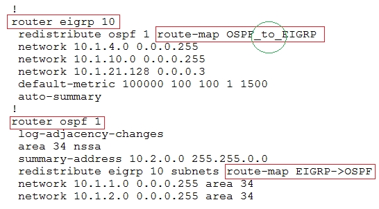
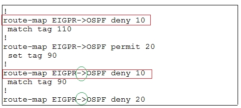
6. From above snap shot it clearly indicates that redistribution done in EIGRP is having problem & by default all routes are denied from ospf to EIGRP"¦ so need to change route-map name.
7. Change required: On R4, in the redistribution of EIGRP routing protocol, we need to change name of route-map to resolve the issue. It references route-map
OSPF_to_EIGRP but the actual route map is called OSPF->EIGRP.
------------------------------------------------------------------------------------------------------------------------------
The implementations group has been using the test bed to do a "˜proof-of-concept"™ that requires both Client 1 and Client 2 to access the WEB Server at
209.65.200.241. After several changes to the network addressing, routing scheme, DHCP services, NTP services, layer 2 connectivity, FHRP services, and device security, a trouble ticket has been opened indicating that Client 1 cannot ping the 209.65.200.241 address.
Use the supported commands to isolated the cause of this fault and answer the following questions.
On which device is the fault condition located?
- A. R1
- B. R2
- C. R3
- D. R4
- E. DSW1
- F. DSW2
- G. ASW1
- H. ASW2
Answer : D
Explanation:
On R4, in the redistribution of EIGRP routing protocol, we need to change name of route-map to resolve the issue. It references route-map OSPF_to_EIGRP but the actual route map is called OSPF->EIGRP.
Question 11
Instructions -
The main screen consists of two parts; the Main scenario and the Topology tabs. The main scenario describes TSHOOT.com test bed. The Topology tabs allow you to display the appropriate and select the trouble ticket.
To complete the item, you will first need to familiarize yourself with the TSHOOT.com test bed by clicking on the master scenario first and then the topologies tabs.
Once you are familiar with the test bed and the topologies, you should start evaluating the trouble ticket. You will be presented with a Trouble Ticket scenario that will describe the fault condition. You will need to determine on which device the fault condition is located, to which technology the fault condition is related, and the solution to each trouble ticket. This will be done by answering three questions.
Ticket Selection -
To begin, click on the Ticket on the Topology tabs.
Some of the questions will require you to use the scroll bar to see all options.
Please note.
Fault Isolation -
Read the ticket scenario to understand the fault condition.
Open the appropriate topology, based upon the ticket scenario.
Open the console of the desired device by clicking on that device in the topology, based upon your troubleshooting methodology.
Use the supported show, ping and trace commands to begin your fault isolation process.
Move to other devices as need by clicking on those devices within the topology.
Fault Identification -
The trouble ticket will include three questions that you will need to answer:
1. Which device contains the fault
2. Which technology the fault condition is related to
3. What is the solution to the issue
To advance to the next question within the ticket click on "Next Question".
When you click "DONE", the trouble ticket will turn RED and will no longer be accessible.
You may also use the "Previous Question" button to review questions within that specific ticket.
To complete a trouble ticket, answer all three questions and click "DONE". This will store your response to the questions. Do not click on "DONE" unless you have answered all questions within the ticket.
Item Completion -
Click the NEXT button on the bottom of the screen once a ticket is RED. This action moves you to the next item.
Topology Overview (Actual Troubleshooting lab design is for below network design)
Client Should have IP 10.2.1.3
EIGRP 100 is running between switch DSW1 & DSW2
OSPF (Process ID 1) is running between R1, R2, R3, R4
Network of OSPF is redistributed in EIGRP
BGP 65001 is configured on R1 with Webserver cloud AS 65002
HSRP is running between DSW1 & DSW2 Switches
The company has created the test bed shown in the layer 2 and layer 3 topology exhibits.
This network consists of four routers, two layer 3 switches and two layer 2 switches.
In the IPv4 layer 3 topology, R1, R2, R3, and R4 are running OSPF with an OSPF process number 1.
DSW1, DSW2 and R4 are running EIGRP with an AS of 10. Redistribution is enabled where necessary.
R1 is running a BGP AS with a number of 65001. This AS has an eBGP connection to AS 65002 in the ISP"™s network. Because the company"™s address space is in the private range.
R1 is also providing NAT translations between the inside (10.1.0.0/16 & 10.2.0.0/16) networks and outside (209.65.0.0/24) network.
ASW1 and ASW2 are layer 2 switches.
NTP is enabled on all devices with 209.65.200.226 serving as the master clock source.
The client workstations receive their IP address and default gateway via R4"™s DHCP server.
The default gateway address of 10.2.1.254 is the IP address of HSRP group 10 which is running on DSW1 and DSW2.
In the IPv6 layer 3 topology R1, R2, and R3 are running OSPFv3 with an OSPF process number 6.
DSW1, DSW2 and R4 are running RIPng process name RIP_ZONE.
The two IPv6 routing domains, OSPF 6 and RIPng are connected via GRE tunnel running over the underlying IPv4 OSPF domain. Redistrution is enabled where necessary.
Recently the implementation group has been using the test bed to do a "˜proof-of-concept"™ on several implementations. This involved changing the configuration on one or more of the devices. You will be presented with a series of trouble tickets related to issues introduced during these configurations.
Note: Although trouble tickets have many similar fault indications, each ticket has its own issue and solution.
Each ticket has 3 sub questions that need to be answered & topology remains same.
Fault is found on which device,
Question-1 -
Fault condition is related to,
Question-2 -
What exact problem is seen & what needs to be done for solution
Question-3 -
===============================================================================
Client is unable to ping IP 209.65.200.241
Solution -
Steps need to follow as below:-
1. When we check on client 1 & Client 2 desktop we are not receiving DHCP address from R4 ipconfig ----- Client will be receiving IP address 10.2.1.3
2. IP 10.2.1.3 will be able to ping from R4 , but cannot ping from R3, R2, R1
3. This clearly shows problem at R4 since EIGRP is between DSW1, DSW2 & R4 and OSPF protocol is running between R4, R3, R2, R1 so routes from R4 are not propagated to R3, R2, R1
4. Since R4 is able to ping 10.2.1.3 it means that routes are received in EIGRP & same needs to be advertised in OSPF to ping from R3, R2, R1.
5. Need to check the routes are being advertised properly or not in OSPF & EIGRP vice-versa.
6. From above snap shot it clearly indicates that redistribution done in EIGRP is having problem & by default all routes are denied from ospf to EIGRP"¦ so need to change route-map name.
7. Change required: On R4, in the redistribution of EIGRP routing protocol, we need to change name of route-map to resolve the issue. It references route-map
OSPF_to_EIGRP but the actual route map is called OSPF->EIGRP.
------------------------------------------------------------------------------------------------------------------------------
The implementations group has been using the test bed to do a "˜proof-of-concept"™ that requires both Client 1 and Client 2 to access the WEB Server at
209.65.200.241. After several changes to the network addressing, routing scheme, DHCP services, NTP services, layer 2 connectivity, FHRP services, and device security, a trouble ticket has been opened indicating that Client 1 cannot ping the 209.65.200.241 address.
Use the supported commands to isolated the cause of this fault and answer the following questions.
The fault condition is related to which technology?
- A. NTP
- B. IP DHCP Server
- C. IPv4 OSPF Routing
- D. IPv4 EIGRP Routing
- E. IPv4 Route Redistribution
- F. IPv6 RIP Routing
- G. IPv6 OSPF Routing
- H. IPv4 and IPv6 Interoperability
- I. IPv4 layer 3 security E
Answer : Explanation
Explanation:
On R4, in the redistribution of EIGRP routing protocol, we need to change name of route-map to resolve the issue. It references route-map OSPF_to_EIGRP but the actual route map is called OSPF->EIGRP.
Question 12
Instructions -
The main screen consists of two parts; the Main scenario and the Topology tabs. The main scenario describes TSHOOT.com test bed. The Topology tabs allow you to display the appropriate and select the trouble ticket.
To complete the item, you will first need to familiarize yourself with the TSHOOT.com test bed by clicking on the master scenario first and then the topologies tabs.
Once you are familiar with the test bed and the topologies, you should start evaluating the trouble ticket. You will be presented with a Trouble Ticket scenario that will describe the fault condition. You will need to determine on which device the fault condition is located, to which technology the fault condition is related, and the solution to each trouble ticket. This will be done by answering three questions.
Ticket Selection -
To begin, click on the Ticket on the Topology tabs.
Some of the questions will require you to use the scroll bar to see all options.
Please note.
Fault Isolation -
Read the ticket scenario to understand the fault condition.
Open the appropriate topology, based upon the ticket scenario.
Open the console of the desired device by clicking on that device in the topology, based upon your troubleshooting methodology.
Use the supported show, ping and trace commands to begin your fault isolation process.
Move to other devices as need by clicking on those devices within the topology.
Fault Identification -
The trouble ticket will include three questions that you will need to answer:
1. Which device contains the fault
2. Which technology the fault condition is related to
3. What is the solution to the issue
To advance to the next question within the ticket click on "Next Question".
When you click "DONE", the trouble ticket will turn RED and will no longer be accessible.
You may also use the "Previous Question" button to review questions within that specific ticket.
To complete a trouble ticket, answer all three questions and click "DONE". This will store your response to the questions. Do not click on "DONE" unless you have answered all questions within the ticket.
Item Completion -
Click the NEXT button on the bottom of the screen once a ticket is RED. This action moves you to the next item.
Topology Overview (Actual Troubleshooting lab design is for below network design)
Client Should have IP 10.2.1.3
EIGRP 100 is running between switch DSW1 & DSW2
OSPF (Process ID 1) is running between R1, R2, R3, R4
Network of OSPF is redistributed in EIGRP
BGP 65001 is configured on R1 with Webserver cloud AS 65002
HSRP is running between DSW1 & DSW2 Switches
The company has created the test bed shown in the layer 2 and layer 3 topology exhibits.
This network consists of four routers, two layer 3 switches and two layer 2 switches.
In the IPv4 layer 3 topology, R1, R2, R3, and R4 are running OSPF with an OSPF process number 1.
DSW1, DSW2 and R4 are running EIGRP with an AS of 10. Redistribution is enabled where necessary.
R1 is running a BGP AS with a number of 65001. This AS has an eBGP connection to AS 65002 in the ISP"™s network. Because the company"™s address space is in the private range.
R1 is also providing NAT translations between the inside (10.1.0.0/16 & 10.2.0.0/16) networks and outside (209.65.0.0/24) network.
ASW1 and ASW2 are layer 2 switches.
NTP is enabled on all devices with 209.65.200.226 serving as the master clock source.
The client workstations receive their IP address and default gateway via R4"™s DHCP server.
The default gateway address of 10.2.1.254 is the IP address of HSRP group 10 which is running on DSW1 and DSW2.
In the IPv6 layer 3 topology R1, R2, and R3 are running OSPFv3 with an OSPF process number 6.
DSW1, DSW2 and R4 are running RIPng process name RIP_ZONE.
The two IPv6 routing domains, OSPF 6 and RIPng are connected via GRE tunnel running over the underlying IPv4 OSPF domain. Redistrution is enabled where necessary.
Recently the implementation group has been using the test bed to do a "˜proof-of-concept"™ on several implementations. This involved changing the configuration on one or more of the devices. You will be presented with a series of trouble tickets related to issues introduced during these configurations.
Note: Although trouble tickets have many similar fault indications, each ticket has its own issue and solution.
Each ticket has 3 sub questions that need to be answered & topology remains same.
Fault is found on which device,
Question-1 -
Fault condition is related to,
Question-2 -
What exact problem is seen & what needs to be done for solution
Question-3 -
===============================================================================
Client is unable to ping IP 209.65.200.241
Solution -
Steps need to follow as below:-
1. When we check on client 1 & Client 2 desktop we are not receiving DHCP address from R4 ipconfig ----- Client will be receiving IP address 10.2.1.3
2. IP 10.2.1.3 will be able to ping from R4 , but cannot ping from R3, R2, R1
3. This clearly shows problem at R4 since EIGRP is between DSW1, DSW2 & R4 and OSPF protocol is running between R4, R3, R2, R1 so routes from R4 are not propagated to R3, R2, R1
4. Since R4 is able to ping 10.2.1.3 it means that routes are received in EIGRP & same needs to be advertised in OSPF to ping from R3, R2, R1.
5. Need to check the routes are being advertised properly or not in OSPF & EIGRP vice-versa.
6. From above snap shot it clearly indicates that redistribution done in EIGRP is having problem & by default all routes are denied from ospf to EIGRP"¦ so need to change route-map name.
7. Change required: On R4, in the redistribution of EIGRP routing protocol, we need to change name of route-map to resolve the issue. It references route-map
OSPF_to_EIGRP but the actual route map is called OSPF->EIGRP.
------------------------------------------------------------------------------------------------------------------------------
The implementations group has been using the test bed to do a "˜proof-of-concept"™ that requires both Client 1 and Client 2 to access the WEB Server at
209.65.200.241. After several changes to the network addressing, routing scheme, DHCP services, NTP services, layer 2 connectivity, FHRP services, and device security, a trouble ticket has been opened indicating that Client 1 cannot ping the 209.65.200.241 address.
Use the supported commands to isolated the cause of this fault and answer the following questions.
Which is the solution to the fault condition?
- A. Under the EIGRP process, delete the redistribute ospf 1 route-map OSPF_ to_ EIGRP command and enter the redistribute ospf 1 route-map OSPF - > EIGRP command.
- B. Under the EIGRP process, delete the redistribute ospf 1 route-map OSPF_ to_ EIGRP command and enter the redistribute ospf 6 metric route-map OSPF - > EIGRP command.
- C. Under the OSPF process, delete the redistribute eigrp10 subnets route-map EIGRP ->OSPF command and enter the redistribute eigrp10 subnets route-map OSPF - > EIGRP command.
- D. Under the OSPF process, delete the redistribute eigrp10 subnets route-map EIGRP ->OSPF command and enter the redistribute eigrp10 subnets route-map EIGPR - > OSPF command.
- E. Under the EIGRP process, delete the redistribute ospf 1 route-map OSPF _to_ EIGRP command and enter redistribute ospf 1 metric 100000 100 100 1 15000 route_ map OSPF _to _EIGRP command.
Answer : A
Explanation:
On R4, in the redistribution of EIGRP routing protocol, we need to change name of route-map to resolve the issue. It references route-map OSPF_to_EIGRP but the actual route map is called OSPF->EIGRP.
Question 13
Instructions -
The main screen consists of two parts; the Main scenario and the Topology tabs. The main scenario describes TSHOOT.com test bed. The Topology tabs allow you to display the appropriate and select the trouble ticket.
To complete the item, you will first need to familiarize yourself with the TSHOOT.com test bed by clicking on the master scenario first and then the topologies tabs.
Once you are familiar with the test bed and the topologies, you should start evaluating the trouble ticket. You will be presented with a Trouble Ticket scenario that will describe the fault condition. You will need to determine on which device the fault condition is located, to which technology the fault condition is related, and the solution to each trouble ticket. This will be done by answering three questions.
Ticket Selection -
To begin, click on the Ticket on the Topology tabs.
Some of the questions will require you to use the scroll bar to see all options.
Please note.
Fault Isolation -
Read the ticket scenario to understand the fault condition.
Open the appropriate topology, based upon the ticket scenario.
Open the console of the desired device by clicking on that device in the topology, based upon your troubleshooting methodology.
Use the supported show, ping and trace commands to begin your fault isolation process.
Move to other devices as need by clicking on those devices within the topology.
Fault Identification -
The trouble ticket will include three questions that you will need to answer:
1. Which device contains the fault
2. Which technology the fault condition is related to
3. What is the solution to the issue
To advance to the next question within the ticket click on "Next Question".
When you click "DONE", the trouble ticket will turn RED and will no longer be accessible.
You may also use the "Previous Question" button to review questions within that specific ticket.
To complete a trouble ticket, answer all three questions and click "DONE". This will store your response to the questions. Do not click on "DONE" unless you have answered all questions within the ticket.
Item Completion -
Click the NEXT button on the bottom of the screen once a ticket is RED. This action moves you to the next item.
Topology Overview (Actual Troubleshooting lab design is for below network design)
Client Should have IP 10.2.1.3
EIGRP 100 is running between switch DSW1 & DSW2

OSPF (Process ID 1) is running between R1, R2, R3, R4
Network of OSPF is redistributed in EIGRP
BGP 65001 is configured on R1 with Webserver cloud AS 65002
HSRP is running between DSW1 & DSW2 Switches
The company has created the test bed shown in the layer 2 and layer 3 topology exhibits.
This network consists of four routers, two layer 3 switches and two layer 2 switches.
In the IPv4 layer 3 topology, R1, R2, R3, and R4 are running OSPF with an OSPF process number 1.
DSW1, DSW2 and R4 are running EIGRP with an AS of 10. Redistribution is enabled where necessary.
R1 is running a BGP AS with a number of 65001. This AS has an eBGP connection to AS 65002 in the ISP"™s network. Because the company"™s address space is in the private range.
R1 is also providing NAT translations between the inside (10.1.0.0/16 & 10.2.0.0/16) networks and outside (209.65.0.0/24) network.
ASW1 and ASW2 are layer 2 switches.
NTP is enabled on all devices with 209.65.200.226 serving as the master clock source.
The client workstations receive their IP address and default gateway via R4"™s DHCP server.
The default gateway address of 10.2.1.254 is the IP address of HSRP group 10 which is running on DSW1 and DSW2.
In the IPv6 layer 3 topology R1, R2, and R3 are running OSPFv3 with an OSPF process number 6.
DSW1, DSW2 and R4 are running RIPng process name RIP_ZONE.
The two IPv6 routing domains, OSPF 6 and RIPng are connected via GRE tunnel running over the underlying IPv4 OSPF domain. Redistrution is enabled where necessary.
Recently the implementation group has been using the test bed to do a "˜proof-of-concept"™ on several implementations. This involved changing the configuration on one or more of the devices. You will be presented with a series of trouble tickets related to issues introduced during these configurations.
Note: Although trouble tickets have many similar fault indications, each ticket has its own issue and solution.
Each ticket has 3 sub questions that need to be answered & topology remains same.
Fault is found on which device,
Question-1 -
Fault condition is related to,
Question-2 -
What exact problem is seen & what needs to be done for solution
Question-3 -
===============================================================================


Client is unable to ping IP 209.65.200.241
Solution -
Steps need to follow as below:-
1. When we check on client 1 & Client 2 desktop we are not receiving DHCP address from R4 ipconfig ----- Client will be receiving IP address 10.2.1.3
2. From Client PC we can ping 10.2.1.254
3. But IP 10.2.1.3 is not able to ping from R4, R3, R2, R1
4. This clearly shows problem at R4 Kindly check routes in EIGRP there are no routes of eigrp.
5. Check the neighborship of EIGRP on R4; there are no neighbor seen from DSW1 & DSW2 check the running config of EIGRP protocol it shows EIGRP AS 1 process"¦. Now check on DSW1 & DSW2
On DSW1 only one Eigrp neighbour is there with DSW2 but its not with R4"¦
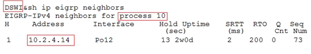
6. From above snapshot & since R4 has EIGRP AS number 1 due to which neighbour is not happening.
7. Change required: On R4, IPV4 EIGRP Routing, need to change the EIGRP AS number from 1 to 10 since DSW1 & DSW2 is configured to be in EIGRP AS number 10.
The implementations group has been using the test bed to do a "˜proof-of-concept"™ that requires both Client 1 and Client 2 to access the WEB Server at
209.65.200.241. After several changes to the network addressing, routing scheme, DHCP services, NTP services, layer 2 connectivity, FHRP services, and device security, a trouble ticket has been opened indicating that Client 1 cannot ping the 209.65.200.241 address.
Use the supported commands to isolated the cause of this fault and answer the following questions.
On which device is the fault condition located?
- A. R1
- B. R2
- C. R3
- D. R4
- E. DSW1
- F. DSW2
- G. ASW1
- H. ASW2 D
Answer : Explanation
Explanation:
The EIGRP AS number configured on R4 is wrong.
Question 14
Instructions -
The main screen consists of two parts; the Main scenario and the Topology tabs. The main scenario describes TSHOOT.com test bed. The Topology tabs allow you to display the appropriate and select the trouble ticket.
To complete the item, you will first need to familiarize yourself with the TSHOOT.com test bed by clicking on the master scenario first and then the topologies tabs.
Once you are familiar with the test bed and the topologies, you should start evaluating the trouble ticket. You will be presented with a Trouble Ticket scenario that will describe the fault condition. You will need to determine on which device the fault condition is located, to which technology the fault condition is related, and the solution to each trouble ticket. This will be done by answering three questions.
Ticket Selection -
To begin, click on the Ticket on the Topology tabs.
Some of the questions will require you to use the scroll bar to see all options.
Please note.
Fault Isolation -
Read the ticket scenario to understand the fault condition.
Open the appropriate topology, based upon the ticket scenario.
Open the console of the desired device by clicking on that device in the topology, based upon your troubleshooting methodology.
Use the supported show, ping and trace commands to begin your fault isolation process.
Move to other devices as need by clicking on those devices within the topology.
Fault Identification -
The trouble ticket will include three questions that you will need to answer:
1. Which device contains the fault
2. Which technology the fault condition is related to
3. What is the solution to the issue
To advance to the next question within the ticket click on "Next Question".
When you click "DONE", the trouble ticket will turn RED and will no longer be accessible.
You may also use the "Previous Question" button to review questions within that specific ticket.
To complete a trouble ticket, answer all three questions and click "DONE". This will store your response to the questions. Do not click on "DONE" unless you have answered all questions within the ticket.
Item Completion -
Click the NEXT button on the bottom of the screen once a ticket is RED. This action moves you to the next item.
Topology Overview (Actual Troubleshooting lab design is for below network design)
Client Should have IP 10.2.1.3
EIGRP 100 is running between switch DSW1 & DSW2
OSPF (Process ID 1) is running between R1, R2, R3, R4
Network of OSPF is redistributed in EIGRP
BGP 65001 is configured on R1 with Webserver cloud AS 65002
HSRP is running between DSW1 & DSW2 Switches
The company has created the test bed shown in the layer 2 and layer 3 topology exhibits.
This network consists of four routers, two layer 3 switches and two layer 2 switches.
In the IPv4 layer 3 topology, R1, R2, R3, and R4 are running OSPF with an OSPF process number 1.
DSW1, DSW2 and R4 are running EIGRP with an AS of 10. Redistribution is enabled where necessary.
R1 is running a BGP AS with a number of 65001. This AS has an eBGP connection to AS 65002 in the ISP"™s network. Because the company"™s address space is in the private range.
R1 is also providing NAT translations between the inside (10.1.0.0/16 & 10.2.0.0/16) networks and outside (209.65.0.0/24) network.
ASW1 and ASW2 are layer 2 switches.
NTP is enabled on all devices with 209.65.200.226 serving as the master clock source.
The client workstations receive their IP address and default gateway via R4"™s DHCP server.
The default gateway address of 10.2.1.254 is the IP address of HSRP group 10 which is running on DSW1 and DSW2.
In the IPv6 layer 3 topology R1, R2, and R3 are running OSPFv3 with an OSPF process number 6.
DSW1, DSW2 and R4 are running RIPng process name RIP_ZONE.
The two IPv6 routing domains, OSPF 6 and RIPng are connected via GRE tunnel running over the underlying IPv4 OSPF domain. Redistrution is enabled where necessary.
Recently the implementation group has been using the test bed to do a "˜proof-of-concept"™ on several implementations. This involved changing the configuration on one or more of the devices. You will be presented with a series of trouble tickets related to issues introduced during these configurations.
Note: Although trouble tickets have many similar fault indications, each ticket has its own issue and solution.
Each ticket has 3 sub questions that need to be answered & topology remains same.
Fault is found on which device,
Question-1 -
Fault condition is related to,
Question-2 -
What exact problem is seen & what needs to be done for solution
Question-3 -
===============================================================================
Client is unable to ping IP 209.65.200.241
Solution -
Steps need to follow as below:-
1. When we check on client 1 & Client 2 desktop we are not receiving DHCP address from R4 ipconfig ----- Client will be receiving IP address 10.2.1.3
2. From Client PC we can ping 10.2.1.254
3. But IP 10.2.1.3 is not able to ping from R4, R3, R2, R1
4. This clearly shows problem at R4 Kindly check routes in EIGRP there are no routes of eigrp.
5. Check the neighborship of EIGRP on R4; there are no neighbor seen from DSW1 & DSW2 check the running config of EIGRP protocol it shows EIGRP AS 1 process"¦. Now check on DSW1 & DSW2
On DSW1 only one Eigrp neighbour is there with DSW2 but its not with R4"¦
6. From above snapshot & since R4 has EIGRP AS number 1 due to which neighbour is not happening.
7. Change required: On R4, IPV4 EIGRP Routing, need to change the EIGRP AS number from 1 to 10 since DSW1 & DSW2 is configured to be in EIGRP AS number 10.
The implementations group has been using the test bed to do a "˜proof-of-concept"™ that requires both Client 1 and Client 2 to access the WEB Server at
209.65.200.241. After several changes to the network addressing, routing scheme, DHCP services, NTP services, layer 2 connectivity, FHRP services, and device security, a trouble ticket has been opened indicating that Client 1 cannot ping the 209.65.200.241 address.
Use the supported commands to isolated the cause of this fault and answer the following questions.
The fault condition is related to which technology?
- A. NTP
- B. IP DHCP Server
- C. IPv4 OSPF Routing
- D. IPv4 EIGRP Routing
- E. IPv4 Route Redistribution
- F. IPv6 RIP Routing
- G. IPv6 OSPF Routing
- H. IPv4 and IPv6 Interoperability
- I. IPv4 layer 3 security
Answer : D
Explanation:
On R4, IPV4 EIGRP Routing, need to change the EIGRP AS number from 1 to 10 since DSW1 & DSW2 is configured to be in EIGRP AS number 10.
Question 15
Instructions -
The main screen consists of two parts; the Main scenario and the Topology tabs. The main scenario describes TSHOOT.com test bed. The Topology tabs allow you to display the appropriate and select the trouble ticket.
To complete the item, you will first need to familiarize yourself with the TSHOOT.com test bed by clicking on the master scenario first and then the topologies tabs.
Once you are familiar with the test bed and the topologies, you should start evaluating the trouble ticket. You will be presented with a Trouble Ticket scenario that will describe the fault condition. You will need to determine on which device the fault condition is located, to which technology the fault condition is related, and the solution to each trouble ticket. This will be done by answering three questions.
Ticket Selection -
To begin, click on the Ticket on the Topology tabs.
Some of the questions will require you to use the scroll bar to see all options.
Please note.
Fault Isolation -
Read the ticket scenario to understand the fault condition.
Open the appropriate topology, based upon the ticket scenario.
Open the console of the desired device by clicking on that device in the topology, based upon your troubleshooting methodology.
Use the supported show, ping and trace commands to begin your fault isolation process.
Move to other devices as need by clicking on those devices within the topology.
Fault Identification -
The trouble ticket will include three questions that you will need to answer:
1. Which device contains the fault
2. Which technology the fault condition is related to
3. What is the solution to the issue
To advance to the next question within the ticket click on "Next Question".
When you click "DONE", the trouble ticket will turn RED and will no longer be accessible.
You may also use the "Previous Question" button to review questions within that specific ticket.
To complete a trouble ticket, answer all three questions and click "DONE". This will store your response to the questions. Do not click on "DONE" unless you have answered all questions within the ticket.
Item Completion -
Click the NEXT button on the bottom of the screen once a ticket is RED. This action moves you to the next item.
Topology Overview (Actual Troubleshooting lab design is for below network design)
Client Should have IP 10.2.1.3
EIGRP 100 is running between switch DSW1 & DSW2
OSPF (Process ID 1) is running between R1, R2, R3, R4
Network of OSPF is redistributed in EIGRP
BGP 65001 is configured on R1 with Webserver cloud AS 65002
HSRP is running between DSW1 & DSW2 Switches
The company has created the test bed shown in the layer 2 and layer 3 topology exhibits.
This network consists of four routers, two layer 3 switches and two layer 2 switches.
In the IPv4 layer 3 topology, R1, R2, R3, and R4 are running OSPF with an OSPF process number 1.
DSW1, DSW2 and R4 are running EIGRP with an AS of 10. Redistribution is enabled where necessary.
R1 is running a BGP AS with a number of 65001. This AS has an eBGP connection to AS 65002 in the ISP"™s network. Because the company"™s address space is in the private range.
R1 is also providing NAT translations between the inside (10.1.0.0/16 & 10.2.0.0/16) networks and outside (209.65.0.0/24) network.
ASW1 and ASW2 are layer 2 switches.
NTP is enabled on all devices with 209.65.200.226 serving as the master clock source.
The client workstations receive their IP address and default gateway via R4"™s DHCP server.
The default gateway address of 10.2.1.254 is the IP address of HSRP group 10 which is running on DSW1 and DSW2.
In the IPv6 layer 3 topology R1, R2, and R3 are running OSPFv3 with an OSPF process number 6.
DSW1, DSW2 and R4 are running RIPng process name RIP_ZONE.
The two IPv6 routing domains, OSPF 6 and RIPng are connected via GRE tunnel running over the underlying IPv4 OSPF domain. Redistrution is enabled where necessary.
Recently the implementation group has been using the test bed to do a "˜proof-of-concept"™ on several implementations. This involved changing the configuration on one or more of the devices. You will be presented with a series of trouble tickets related to issues introduced during these configurations.
Note: Although trouble tickets have many similar fault indications, each ticket has its own issue and solution.
Each ticket has 3 sub questions that need to be answered & topology remains same.
Fault is found on which device,
Question-1 -
Fault condition is related to,
Question-2 -
What exact problem is seen & what needs to be done for solution
Question-3 -
===============================================================================
Client is unable to ping IP 209.65.200.241
Solution -
Steps need to follow as below:-
1. When we check on client 1 & Client 2 desktop we are not receiving DHCP address from R4 ipconfig ----- Client will be receiving IP address 10.2.1.3
2. From Client PC we can ping 10.2.1.254
3. But IP 10.2.1.3 is not able to ping from R4, R3, R2, R1
4. This clearly shows problem at R4 Kindly check routes in EIGRP there are no routes of eigrp.
5. Check the neighborship of EIGRP on R4; there are no neighbor seen from DSW1 & DSW2 check the running config of EIGRP protocol it shows EIGRP AS 1 process"¦. Now check on DSW1 & DSW2
On DSW1 only one Eigrp neighbour is there with DSW2 but its not with R4"¦
6. From above snapshot & since R4 has EIGRP AS number 1 due to which neighbour is not happening.
7. Change required: On R4, IPV4 EIGRP Routing, need to change the EIGRP AS number from 1 to 10 since DSW1 & DSW2 is configured to be in EIGRP AS number 10.
The implementations group has been using the test bed to do a "˜proof-of-concept"™ that requires both Client 1 and Client 2 to access the WEB Server at
209.65.200.241. After several changes to the network addressing, routing scheme, DHCP services, NTP services, layer 2 connectivity, FHRP services, and device security, a trouble ticket has been opened indicating that Client 1 cannot ping the 209.65.200.241 address.
Use the supported commands to isolated the cause of this fault and answer the following questions.
What is the solution to the fault condition?
- A. Disable auto summary on the EIGRP process
- B. Enable EIGRP on the FastEthernet0/0 and FastEthernet0/1 interface using the no passive-interface command.
- C. Change the AS number on the EIGRP routing process from 1 to 10 to much the AS number used on DSW1 and DSW2.
- D. Under the EIGRP process, delete the network 10.1.4.0 0.0.0.255 command and enter the network 10.1.4.4 0.0.0.252 and 10.1.4.8 0.0.0.252 commands.
Answer : C
Explanation:
On R4, IPV4 EIGRP Routing, need to change the EIGRP AS number from 1 to 10 since DSW1 & DSW2 is configured to be in EIGRP AS number 10.